

Project Overview
Arduino Nano + LCD1602 auto-ranging ohmmeter: Build an Arduino Nano resistance meter that switches between five reference resistors and displays the best-range reading (Ω, kΩ, or MΩ) on a 16x2 LCD.
A voltage divider with one known resistor can only measure accurately across a limited decade. This project fixes that the way real meters do: it tries multiple reference resistors (100Ω to 1MΩ) and keeps the range that lands closest to mid-scale on the ADC, where readings are most trustworthy.
- Time: ~45 minutes
- Skill level: Intermediate
- What you will build: A five-range, auto-selecting resistance meter with open/short detection, unit-aware formatting, and a simple calibration table.

Parts List
From ShillehTek
- Arduino Nano V3.0 Pre-Soldered - runs the ADC measurements and controls the reference ranges
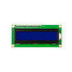
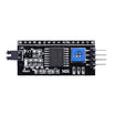
- LCD1602 16x2 Display + PCF8574 I2C Adapter - displays resistance and the selected range
- Resistor Kit (1 % metal film) - provides 100Ω, 1kΩ, 10kΩ, 100kΩ, 1MΩ references and test resistors
- 830-Point Breadboard - quick prototyping for the reference ladder
- Dupont Jumper Wires - wiring between Arduino, resistors, and LCD
External
- Two alligator-clip leads for probes (optional)
Note: only measure resistors that are out of circuit and unpowered. In a live circuit the meter reads the whole network (and a 5 V probe can upset it). On a charged capacitor the ADC pin can be damaged. Discharge, remove, then measure.
Step-by-Step Guide
Step 1 - Build the Reference Ladder
Goal: Create five known resistors that all meet at one sense node.
What to do: Pick a breadboard row as the sense node. Connect 100Ω from D8 to the node, 1kΩ from D9, 10kΩ from D10, 100kΩ from D11, and 1MΩ from D12. Connect A0 to the node.
Connect the unknown resistor between the node and GND (use two clip leads as probes). Wire the I2C LCD as follows: SDA to A4, SCL to A5, VCC to 5V, and GND to GND.

Expected result: A star of five resistors around one row, plus two probe leads from the node to GND for measuring unknown resistors.
Step 2 - How Auto-Ranging Works
Goal: Understand the measurement method before uploading the sketch.
What to do: The sketch drives one reference pin HIGH (5 V) and sets the other four pins to INPUT (high-impedance). That effectively disconnects the unused reference resistors, so exactly one voltage divider exists: Rref on top, Rx on the bottom, and A0 in the middle.
The ADC reading gives:
Rx = Rref × adc / (1023 - adc)
The code repeats this for all five references and keeps the one whose ADC reading is closest to 512 (mid-scale). Mid-scale is chosen because a one-count ADC error changes the result the least there. No diodes or analog switches are required because tri-stating the pins provides the isolation.
Expected result: You understand why a 10kΩ reference is inaccurate for measuring 10Ω, and how this design avoids that by selecting the best range automatically.
Step 3 - Upload the Sketch
Goal: Program the Arduino Nano to measure resistance, select the best range, and print to the LCD.
Code:
#include <LiquidCrystal_I2C.h>
LiquidCrystal_I2C lcd(0x27, 16, 2);

const int PIN[5] = {8, 9, 10, 11, 12};
// Measured reference values. Add ~30 ohms to the lowest one for the pin's own output resistance.
float REF[5] = {130.0, 1000.0, 10000.0, 100000.0, 1000000.0};
const char* NAME[5] = {"100", "1k", "10k", "100k", "1M"};
const int SENSE = A0;

int readRange(int r) {
  pinMode(PIN[r], OUTPUT); digitalWrite(PIN[r], HIGH);   // only this reference is "connected"
  delay(5);                                              // let the high ranges settle
  long s = 0; for (int i = 0; i < 16; i++) s += analogRead(SENSE);
  digitalWrite(PIN[r], LOW); pinMode(PIN[r], INPUT);     // back to high-impedance
  return s / 16;
}

void printOhms(float r) {
  if (r < 1000)     { lcd.print(r, 1);         lcd.print(" ");  }
  else if (r < 1e6) { lcd.print(r / 1000, 2);  lcd.print(" k"); }
  else              { lcd.print(r / 1e6, 2);   lcd.print(" M"); }
  lcd.write(0xF4);                                       // the omega symbol in the LCD's character ROM
  lcd.print("      ");
}

void setup() {
  lcd.init(); lcd.backlight();
  for (int i = 0; i < 5; i++) pinMode(PIN[i], INPUT);
}

void loop() {
  int adc[5], lo = 1023, hi = 0, best = 0;
  for (int r = 0; r < 5; r++) {
    adc[r] = readRange(r);
    lo = min(lo, adc[r]); hi = max(hi, adc[r]);
    if (abs(adc[r] - 512) < abs(adc[best] - 512)) best = r;   // closest to mid-scale wins
  }
  lcd.setCursor(0, 0);
  if (lo >= 1015)      lcd.print("Open  (> 5 M)   ");         // every range reads ~5 V
  else if (hi <= 4)    lcd.print("Short / < 2 ohm ");         // every range reads ~0 V
  else printOhms(REF[best] * adc[best] / (1023.0 - adc[best]));
  lcd.setCursor(0, 1);
  lcd.print("Range "); lcd.print(NAME[best]); lcd.print("  adc "); lcd.print(adc[best]); lcd.print("   ");
  delay(300);
}
What to do: Install the LiquidCrystal_I2C library, upload the sketch, then clip a 4.7kΩ resistor between the probes.
Expected result: You should see something like “4.68 kΩ” (or close) on the top line and “Range 10k adc 327” underneath. Try 47Ω, 220kΩ, and 2.2MΩ; the range label should change automatically. Open probes should display “Open”, and touching the probes together should display “Short”.
Step 4 - Calibrate
Goal: Improve accuracy from about ±5% toward about ±1%.
What to do: The references are 1% parts, but the Arduino pin adds about 25 to 40Ω in series when HIGH, which matters on the 100Ω range. That is why REF[0] starts at 130. Measure a known resistor on each range (a second 1% resistor of similar value is a fine standard) and adjust each REF[] entry until the display matches.
The 1MΩ range is the twitchiest. Keep leads short and keep fingers off the probes, since your body can be a few hundred kΩ.
Expected result: Readings within a couple of percent across all five ranges.
Step 5 - Improve It
Goal: Add useful meter-style features.
What to do: Add a hold button that freezes the reading. Print the nearest E12 standard value and color code beneath the measurement. Average ten readings for a steadier display. For better low-ohm accuracy, use the ADC’s 1.1 V internal reference on the lowest range (analogReference(INTERNAL)) with a smaller reference resistor. Log to Serial to sort a tray of unmarked resistors.
Expected result: A homemade instrument you will reach for regularly.
Conclusion
Using five reference resistors and Arduino pin tri-stating, you built an Arduino Nano auto-ranging ohmmeter that keeps the ADC near mid-scale and displays the result on an LCD1602 in Ω, kΩ, or MΩ. This is the same core ranging idea used inside common bench and handheld multimeters.
Want the exact parts used in this build? Grab them from ShillehTek.com. If you want help customizing this project or building something for your product, check out our IoT consulting services.
Credits
All photos and images in this tutorial are credited to Mirko Pavleski (mircemk) on Hackster.io. The original guide by Mirko Pavleski served as the reference for this ShillehTek version. We thank them for their excellent work in the maker community.






.png?v=25000753014097803521791168436)

.png?v=68677308723310773341791168436)


