

Project Overview
Arduino IR receiver remote control: In this project, you will use an Arduino (such as an Arduino Uno) with an IR receiver module to decode any IR remote button press and toggle LEDs or a relay to switch larger loads.
Point a spare remote at a low-cost receiver, read the button codes in Serial, then map those codes to outputs. Start with LEDs for safe testing, then swap an LED output for a relay module to control real appliances.
- Time: ~45 minutes
- Skill level: Beginner
- What you will build: A remote-controlled Arduino: one button toggles one LED, another toggles a second, and the same pattern scales to relays and other loads.

Parts List
From ShillehTek
- Arduino Uno R3 Super Starter Kit - includes the IR remote and receiver used here, plus LEDs and resistors
- Resistor Kit - 220Ω for each LED
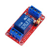
- 1-Channel 5V Relay Module - upgrade from LEDs to switching real loads
- 400-Point Breadboard - for quick prototyping
- Dupont Jumper Wires - for wiring the receiver, LEDs, and relay
External
- Any spare IR remote also works - TV, soundbar, air conditioner
Note: IR is line-of-sight. The receiver demodulates 38 kHz infrared bursts into a digital signal your Arduino can decode, and receiver pin order can vary by brand, so confirm your module pinout before powering it.
Step-by-Step Guide
Step 1 - Wire the Receiver and LEDs
Goal: Connect the IR receiver and two LED outputs for testing.
What to do: Wire the IR receiver module: OUT to D3, VCC to 5V, GND to GND (check your module's pinout, since the three legs vary between brands). Wire LED 1 to D8 through a 220Ω resistor, and LED 2 to D9 through a 220Ω resistor. Connect both LED cathodes to GND.
Expected result: The receiver and LED indicators are ready for code testing.
Step 2 - Discover Your Remote's Codes
Goal: Identify the command values sent by your specific remote buttons.
What to do: Install the IRremote library and upload a simple decoder sketch that prints incoming commands to Serial. Press each button you want to use and write down the hex command value shown in the Serial Monitor.
Code:
#include <IRremote.hpp>   // IRremote v3/v4 API

void setup() {
  Serial.begin(115200);
  IrReceiver.begin(3, ENABLE_LED_FEEDBACK);   // receiver on D3
}

void loop() {
  if (IrReceiver.decode()) {
    Serial.print("Button command: 0x");
    Serial.println(IrReceiver.decodedIRData.command, HEX);
    IrReceiver.resume();                       // ready for next press
  }
}
Expected result: A unique hex code appears in the Serial Monitor for every button you press.
Step 3 - Map Buttons to Actions
Goal: Toggle two outputs with two remote buttons.
What to do: Replace BTN_1 and BTN_2 with the command values you recorded in Step 2. Upload the sketch and test. The code ignores NEC repeat frames so one button press equals one toggle.
Code:
#include <IRremote.hpp>

#define BTN_1 0x45      // replace with YOUR codes from Step 2
#define BTN_2 0x46

bool led1 = false, led2 = false;

void setup() {
  IrReceiver.begin(3, ENABLE_LED_FEEDBACK);
  pinMode(8, OUTPUT);
  pinMode(9, OUTPUT);
}

void loop() {
  if (IrReceiver.decode()) {
    // ignore NEC auto-repeat frames so one press = one toggle
    if (!(IrReceiver.decodedIRData.flags & IRDATA_FLAGS_IS_REPEAT)) {
      switch (IrReceiver.decodedIRData.command) {
        case BTN_1: led1 = !led1; digitalWrite(8, led1); break;
        case BTN_2: led2 = !led2; digitalWrite(9, led2); break;
      }
    }
    IrReceiver.resume();
  }
}
Expected result: Button 1 toggles LED 1 and button 2 toggles LED 2, one toggle per press.
Step 4 - Swap an LED for a Relay
Goal: Use the same IR control pattern to switch a higher-power load.
What to do: Move one Arduino output from the LED circuit to the relay module's signal pin. Power the relay module with 5V and GND. Wire a lamp or fan through the relay contacts. Keep the same code and use the same button to switch the relay.
Expected result: The remote button toggles the relay, letting you switch an appliance through the relay contacts.
Step 5 - Ideas That Use the Same Pattern
Goal: Apply the decode-and-switch approach to other projects.
What to do: Reuse the same receiver and decoding logic for projects like PWM dimming, an IR-controlled robot (map arrow buttons to motor commands), WS2812 light scenes, or a multi-button IR keypad for a project box.
Expected result: You have a repeatable input method you can map to many different outputs and behaviors.
Conclusion
Using an Arduino with an IR receiver and the IRremote library, you decoded remote button commands and mapped them to toggling LEDs and a relay. This gives you an inexpensive, reliable wireless control method for prototypes and real switching projects.
Want the exact parts used in this build? Grab them from ShillehTek.com. If you want help customizing this project or building something for your product, check out our IoT consulting services.
Credits
All photos and images in this tutorial are credited to Electronics Champ on Hackster.io. The original guide by Electronics Champ served as the reference for this ShillehTek version. We thank them for their excellent work in the maker community.






.png?v=25000753014097803521791168436)

.png?v=68677308723310773341791168436)


