

Project Overview
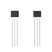
Arduino + 49E Linear Hall Effect Sensor: In this tutorial you connect a 49E-family linear Hall effect sensor module to an Arduino and get a live readout of magnetic field strength (analog) plus a threshold detection signal (digital) side by side.
The Hall effect is the small voltage that appears across a conductor when a magnetic field passes through it perpendicular to the current. A 49E-family linear Hall sensor turns that physics into a usable signal: its output voltage swings above or below a midpoint depending on the field's strength and polarity.
- Time: 30 minutes
- Skill level: Beginner
- What you will build: A live magnetic field readout showing analog strength and digital detection side by side.

Parts List
From ShillehTek
- 49E Linear Hall Effect Magnetic Sensor - provides analog field strength and (module) digital threshold output
- Arduino Nano V3 - or any Arduino UNO-compatible board
- 120pcs 20cm Dupont Jumper Wires - quick breadboard wiring
- 400-Point Solderless Breadboard - prototyping connections
External
- A permanent magnet for testing (a speaker magnet with its radial field is great for experiments)
Note: The bare 49E (SS49E) outputs an analog voltage centered around VCC/2 with no field. Module versions add an LM393 comparator with a trimmer so you also get a digital threshold output.
Step-by-Step Guide
Step 1 - Understand the Two Outputs
Goal: Know what each pin tells you.
What to do: The module runs on 5V and exposes two signals. The analog output follows the magnetic field continuously. With no magnet you read a mid-scale value, one pole pushes the reading up, and the opposite pole pulls it down, so you can sense both strength and polarity. The digital output flips HIGH or LOW when the field crosses a threshold you set with the onboard trimmer, which is useful for simple presence detection.
Expected result: Analog = measurement, digital = switch.
Step 2 - Wire It to the Arduino
Goal: Connect power plus analog and digital signals.
What to do: Make these connections:
Module + (VCC) -> 5V
Module G (GND) -> GND
Analog out A0  -> Arduino A0
Digital out D0 -> Arduino D2
Expected result: The sensor is powered and both outputs are connected to the Arduino.
Step 3 - Upload the Test Sketch
Goal: Stream both readings to the Serial Monitor.
What to do: Upload SurtrTech's test sketch. It prints the analog value and digital state on one line each pass:
/* Displays both Analog and Digital values from a hall sensor module */
#define Hall_Sensor A0    // analog output
#define Hall_Sensor_D 2   // digital output

int Val1 = 0, Val2 = 0;

void setup() {
  Serial.begin(9600);
  pinMode(Hall_Sensor_D, INPUT);
}

void loop() {
  Val1 = analogRead(Hall_Sensor);
  Serial.print(Val1);
  Val2 = digitalRead(Hall_Sensor_D);
  Serial.print("\t");
  Serial.println(Val2);
}
Expected result: Two columns in the Serial Monitor: analog level and digital 0/1.
Step 4 - Explore with a Magnet
Goal: See polarity and strength in the numbers.
What to do: Move a magnet around the sensor and watch the analog column. In the original test with a speaker magnet, readings swung from roughly 470 to 620 depending on which pole faced the sensor and how close it was. Turn the trimmer until the digital column flips exactly at the distance you care about.
Expected result: Readings rise toward one pole, fall toward the other, and the digital output trips at your chosen threshold.
Conclusion
You wired a 49E-family linear Hall effect sensor module to an Arduino and read magnetic field strength, polarity, and a clean digital threshold output. From here you can build an RPM counter (magnet on a wheel), position sensing for a jig, or a contactless switch with no moving parts.
Want the exact parts used in this build? Grab them from ShillehTek.com. If you want help customizing this project or building something for your product, check out our IoT consulting services.





.png?v=25000753014097803521791168436)

.png?v=68677308723310773341791168436)


