Overview
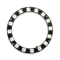
This 90mm ring carries 24 WS2812 addressable RGB LEDs — each one an independent pixel with its own tiny controller chip baked inside. One data wire from your microcontroller sets the color and brightness of every LED individually: whole-ring rainbows, spinning comets, clock faces, audio meters, or a single status pixel — all from one GPIO pin. No multiplexing, no driver ICs, no PWM juggling; the pixels latch their colors and hold them until told otherwise.
The 24-pixel count and 90mm diameter hit a sweet spot: big enough to read as a proper dial or halo (clocks, gauges, speaker surrounds, camera ring lights, infinity mirrors), small enough to run from a modest 5V supply. Solder pads on the back bring out power (5V/GND) and the data chain — DI in, DO out — so rings can be daisy-chained into longer runs by wiring one ring's DO to the next ring's DI.
Library support is universal: Adafruit NeoPixel and FastLED on Arduino/ESP32, the built-in neopixel module in MicroPython on ESP32 and Pico, and rpi_ws281x on the Raspberry Pi. The only discipline WS2812s demand is electrical: a 330-470 ohm resistor in the data line, a big capacitor across power, and a supply sized for the worst case — about 60 mA per LED at full white, or ~1.4 A for the whole ring.
At a Glance
Specifications
| Parameter | Value |
| LED Type | WS2812 (WS2812B-class) integrated RGB + driver, 5050 package |
| LED Count | 24, evenly spaced on the ring |
| Outer Diameter | ~90 mm |
| Supply Voltage | 5V DC (4.5 - 5.5V) |
| Current Draw | ~1 mA idle per LED; up to ~60 mA per LED at full white (~1.4 A total) |
| Data Protocol | Single-wire, 800 kHz, strict timing (library-handled) |
| Color Depth | 24-bit (8 bits per channel, GRB order) |
| Pads | DI (data in), DO (data out), 5V/VCC, GND |
| Recommended Extras | 330-470 ohm resistor on DI; 470-1000 uF capacitor across 5V/GND |
| Logic Level | 5V nominal; 3.3V data usually works (level shifter for reliability) |
| Viewing | Individually addressable — any LED any color at any time |
Wiring Guide
Three connections do everything: 5V and GND to the power pads, and your GPIO to DI (data flows one way around the ring — into DI, out of DO). Put a 330-470 ohm resistor close to DI and a 470-1000 uF electrolytic across the power pads. Always connect grounds between the LED supply and the microcontroller.
Arduino Wiring
| Ring Pad | Arduino Pin | Details |
|---|---|---|
| DI | D6 via 330 ohm | Data input |
| 5V | 5V (demos) / external 5V 2A (full brightness) | 1000 uF cap across supply |
| GND | GND | Common with external supply |
ESP32 Wiring
| Ring Pad | ESP32 Pin | Details |
|---|---|---|
| DI | GPIO 13 via 330 ohm | Any output GPIO works |
| 5V | VIN (USB 5V) or external 5V | Not 3V3 — LEDs want 5V power |
| GND | GND |
Raspberry Pi Wiring
| Ring Pad | Pi Pin | Details |
|---|---|---|
| DI | Pin 12 (GPIO 18) via 330 ohm | PWM0 — required by rpi_ws281x |
| 5V | Pin 2 (5V) for demos / external 5V 2A | 1000 uF cap recommended |
| GND | Pin 6 (GND) |
Raspberry Pi Pico Wiring
| Ring Pad | Pico Pin | Details |
|---|---|---|
| DI | GP0 (pin 1) via 330 ohm | PIO drives the timing |
| 5V | VBUS (pin 40) or external 5V | USB 5V handles medium brightness |
| GND | GND (pin 38) |
Code Examples
Each example runs the same three-scene demo — a spinning comet chase, a full-ring rainbow, and a "clock hand" sweep — with brightness capped to stay USB-friendly. Raise the brightness only on an external supply.
Arduino
// WS2812 24-LED Ring - Arduino Example
// DI->D6 via 330 ohm, 5V->5V, GND->GND
// Library: "Adafruit NeoPixel" (Library Manager)

#include <Adafruit_NeoPixel.h>

#define PIN        6
#define NUM_LEDS   24

Adafruit_NeoPixel ring(NUM_LEDS, PIN, NEO_GRB + NEO_KHZ800);

void setup() {
  ring.begin();
  ring.setBrightness(60);            // 0-255; keep low on USB power
  ring.show();
}

void comet(uint32_t color, int loops) {
  for (int t = 0; t < loops * NUM_LEDS; t++) {
    ring.clear();
    for (int tail = 0; tail < 6; tail++) {
      int i = (t - tail + NUM_LEDS * 8) % NUM_LEDS;
      uint8_t fade = 255 >> tail;
      uint8_t r = (uint8_t)(color >> 16) * fade / 255;
      uint8_t g = (uint8_t)(color >> 8)  * fade / 255;
      uint8_t b = (uint8_t)(color)       * fade / 255;
      ring.setPixelColor(i, r, g, b);
    }
    ring.show();
    delay(40);
  }
}

void rainbow(int loops) {
  for (int j = 0; j < 256 * loops; j++) {
    for (int i = 0; i < NUM_LEDS; i++) {
      ring.setPixelColor(i, ring.gamma32(
        ring.ColorHSV((i * 65536L / NUM_LEDS + j * 256) & 0xFFFF)));
    }
    ring.show();
    delay(10);
  }
}

void clockSweep(int loops) {
  for (int t = 0; t < loops * NUM_LEDS; t++) {
    ring.clear();
    ring.setPixelColor(t % NUM_LEDS, 255, 40, 0);      // hand
    ring.setPixelColor(0, 40, 40, 40);                 // 12 o'clock mark
    ring.show();
    delay(120);
  }
}

void loop() {
  comet(ring.Color(0, 120, 255), 3);
  rainbow(2);
  clockSweep(2);
}
ESP32 (MicroPython)
# WS2812 24-LED Ring - ESP32 MicroPython Example
# DI->GPIO 13 via 330 ohm, 5V->VIN, GND->GND

from machine import Pin
import neopixel, time

NUM = 24
ring = neopixel.NeoPixel(Pin(13), NUM)
BRIGHT = 0.25                      # global brightness cap

def scale(c):
    return tuple(int(x * BRIGHT) for x in c)

def wheel(pos):
    pos %= 256
    if pos < 85:  return (255 - pos * 3, pos * 3, 0)
    if pos < 170: pos -= 85; return (0, 255 - pos * 3, pos * 3)
    pos -= 170;   return (pos * 3, 0, 255 - pos * 3)

def comet(color, loops=3):
    for t in range(loops * NUM):
        ring.fill((0, 0, 0))
        for tail in range(6):
            i = (t - tail) % NUM
            fade = 1 / (tail + 1)
            ring[i] = scale(tuple(int(x * fade) for x in color))
        ring.write()
        time.sleep_ms(40)

def rainbow(loops=2):
    for j in range(256 * loops):
        for i in range(NUM):
            ring[i] = scale(wheel(i * 256 // NUM + j))
        ring.write()
        time.sleep_ms(10)

def clock_sweep(loops=2):
    for t in range(loops * NUM):
        ring.fill((0, 0, 0))
        ring[t % NUM] = scale((255, 40, 0))
        ring[0] = scale((40, 40, 40))
        ring.write()
        time.sleep_ms(120)

while True:
    comet((0, 120, 255))
    rainbow()
    clock_sweep()
Raspberry Pi (Python)
#!/usr/bin/env python3
# WS2812 24-LED Ring - Raspberry Pi Example (rpi_ws281x)
# DI->GPIO18 (pin 12) via 330 ohm; run with: sudo python3 ring24_rpi.py
# Install: sudo pip3 install rpi_ws281x  (and disable onboard audio)

import time
from rpi_ws281x import PixelStrip, Color

NUM = 24
strip = PixelStrip(NUM, 18, brightness=60)   # GPIO 18, brightness 0-255
strip.begin()

def comet(color, loops=3):
    for t in range(loops * NUM):
        for i in range(NUM):
            strip.setPixelColor(i, 0)
        for tail in range(6):
            i = (t - tail) % NUM
            fade = 255 // (tail + 1)
            r = ((color >> 16) & 0xFF) * fade // 255
            g = ((color >> 8) & 0xFF) * fade // 255
            b = (color & 0xFF) * fade // 255
            strip.setPixelColor(i, Color(r, g, b))
        strip.show()
        time.sleep(0.04)

def wheel(pos):
    pos %= 256
    if pos < 85:  return Color(255 - pos * 3, pos * 3, 0)
    if pos < 170: pos -= 85; return Color(0, 255 - pos * 3, pos * 3)
    pos -= 170;   return Color(pos * 3, 0, 255 - pos * 3)

def rainbow(loops=2):
    for j in range(256 * loops):
        for i in range(NUM):
            strip.setPixelColor(i, wheel(i * 256 // NUM + j))
        strip.show()
        time.sleep(0.01)

try:
    while True:
        comet(0x0078FF)
        rainbow()
except KeyboardInterrupt:
    for i in range(NUM):
        strip.setPixelColor(i, 0)
    strip.show()
    print("Stopped by user")
Raspberry Pi Pico (MicroPython)
# WS2812 24-LED Ring - Pico MicroPython Example
# DI->GP0 via 330 ohm, 5V->VBUS, GND->GND

from machine import Pin
import neopixel, time

NUM = 24
ring = neopixel.NeoPixel(Pin(0), NUM)
BRIGHT = 0.25

def scale(c):
    return tuple(int(x * BRIGHT) for x in c)

def breathe(color, cycles=3):
    for _ in range(cycles):
        for level in list(range(0, 100)) + list(range(100, 0, -1)):
            ring.fill(tuple(int(x * level / 100 * BRIGHT) for x in color))
            ring.write()
            time.sleep_ms(8)

def spinner(color, loops=4):
    for t in range(loops * NUM):
        ring.fill((0, 0, 0))
        for k in range(3):                      # 3 arms
            ring[(t + k * NUM // 3) % NUM] = scale(color)
        ring.write()
        time.sleep_ms(50)

while True:
    spinner((0, 255, 80))
    breathe((120, 0, 255))