Overview
The SW-520D module is the simplest motion detector you can wire: a gold-plated cylinder containing two tiny conductive balls that either bridge a pair of contacts or roll away from them as the module tilts. Sit it flat and the circuit is closed; tip it past roughly 15-45 degrees and the balls roll off, the circuit opens, and the D0 pin flips state. No axes, no registers, no calibration — just "upright" or "not upright."
The onboard LM393 comparator turns the raw ball-switch contact into a clean digital output, with a sensitivity trimpot to set the threshold and two indicator LEDs: PWR for supply and a status LED that mirrors D0, so you can watch it trigger before writing a line of code. Because output is a plain logic level, it works identically at 3.3V and 5V and connects to any GPIO with three wires.
Classic jobs: tip-over protection for heaters and machines, tamper/movement alarms on doors, cases, and packages, orientation detection for handheld gadgets, vibration-adjacent sensing on the cheap, and HVAC or appliance interlocks. If you need to know the angle, that's accelerometer territory (ADXL345/MPU6050) — the SW-520D's charm is answering the binary question instantly, for pennies, with zero code overhead.
At a Glance
Specifications
| Parameter | Value |
| Sensing Element | SW-520D double-ball tilt switch, gold-plated can |
| Comparator | LM393 dual comparator with trimpot threshold |
| Supply Voltage | 3.3V - 5V DC |
| Current Draw | ~15 mA (mostly the LEDs) |
| Output | Digital, push-pull logic level on D0 |
| Logic Sense | Level (balls bridging) = LOW; tilted = HIGH (typical boards) |
| Trigger Angle | ~15° begins to open, fully open by ~45° |
| Response | Instant; contacts bounce for ~10-50 ms while rolling |
| Indicators | PWR-LED (power), DO-LED (mirrors output) |
| Operating Temperature | -25°C to +80°C |
| Board Size | ~32 x 14 mm, single mounting hole |
Pinout Diagram
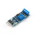
Three pins on the right edge: VCC, GND, and D0. The gold cylinder at the corner is the tilt switch itself — mount the board so the cylinder's axis is vertical when your device is "upright." The blue trimpot adjusts the comparator threshold, and the DO-LED lights the moment the output trips, which makes aiming and testing a hands-on affair.

Wiring Guide
Arduino Wiring
| Module Pin | Arduino Pin |
|---|---|
| VCC | 5V |
| GND | GND |
| D0 | D2 |
ESP32 Wiring
| Module Pin | ESP32 Pin | Details |
|---|---|---|
| VCC | 3V3 | Keeps D0 at 3.3V logic |
| GND | GND | |
| D0 | GPIO 27 | Any input-capable GPIO |
Raspberry Pi Wiring
| Module Pin | Pi Pin | Details |
|---|---|---|
| VCC | Pin 1 (3.3V) | NOT 5V — protects the GPIO |
| GND | Pin 6 (GND) | |
| D0 | Pin 11 (GPIO 17) |
Raspberry Pi Pico Wiring
| Module Pin | Pico Pin |
|---|---|
| VCC | 3V3(OUT) (pin 36) |
| GND | GND (pin 38) |
| D0 | GP16 (pin 21) |
Code Examples
Each example debounces the ball-switch chatter in software and reports every stable transition — "TILTED!" and "Level again" — the pattern you'd wire into any alarm or safety cutoff.
Arduino
// SW-520D Tilt Switch Module - Arduino Example (debounced)
// D0->D2, VCC->5V, GND->GND

const int tiltPin = 2;
const unsigned long DEBOUNCE_MS = 60;

int stableState;
int lastReading;
unsigned long lastChange = 0;

void setup() {
  Serial.begin(9600);
  pinMode(tiltPin, INPUT);
  stableState = lastReading = digitalRead(tiltPin);
  Serial.println("Tilt sensor ready - tip me over!");
}

void loop() {
  int reading = digitalRead(tiltPin);

  if (reading != lastReading) {
    lastChange = millis();          // edge seen - restart timer
    lastReading = reading;
  }

  if (millis() - lastChange > DEBOUNCE_MS && reading != stableState) {
    stableState = reading;
    if (stableState == HIGH) {
      Serial.println("TILTED!");
    } else {
      Serial.println("Level again");
    }
  }
}
ESP32 (MicroPython)
# SW-520D Tilt Switch Module - ESP32 MicroPython Example
# D0->GPIO 27, VCC->3V3, GND->GND

from machine import Pin
import time

tilt = Pin(27, Pin.IN)

DEBOUNCE_MS = 60
stable = tilt.value()
last_reading = stable
last_change = time.ticks_ms()

print("Tilt sensor ready - tip me over!")
while True:
    reading = tilt.value()

    if reading != last_reading:
        last_change = time.ticks_ms()
        last_reading = reading

    if (time.ticks_diff(time.ticks_ms(), last_change) > DEBOUNCE_MS
            and reading != stable):
        stable = reading
        print("TILTED!" if stable else "Level again")

    time.sleep_ms(5)
Raspberry Pi (Python)
#!/usr/bin/env python3
# SW-520D Tilt Switch Module - Raspberry Pi Example
# D0->GPIO17 (pin 11), VCC->3.3V, GND->GND

import RPi.GPIO as GPIO
import time

TILT_PIN = 17
DEBOUNCE_S = 0.06

GPIO.setmode(GPIO.BCM)
GPIO.setup(TILT_PIN, GPIO.IN)

stable = GPIO.input(TILT_PIN)
last_reading = stable
last_change = time.time()

print("Tilt sensor ready - tip me over!")
try:
    while True:
        reading = GPIO.input(TILT_PIN)

        if reading != last_reading:
            last_change = time.time()
            last_reading = reading

        if time.time() - last_change > DEBOUNCE_S and reading != stable:
            stable = reading
            print("TILTED!" if stable else "Level again")

        time.sleep(0.005)
except KeyboardInterrupt:
    GPIO.cleanup()
    print("Stopped by user")
Raspberry Pi Pico (MicroPython)
# SW-520D Tilt Switch Module - Pico MicroPython Example
# D0->GP16, VCC->3V3(OUT), GND->GND
# Onboard LED mirrors the tilt state.

from machine import Pin
import time

tilt = Pin(16, Pin.IN)
led = Pin("LED", Pin.OUT)

DEBOUNCE_MS = 60
stable = tilt.value()
last_reading = stable
last_change = time.ticks_ms()

print("Tilt sensor ready - tip me over!")
while True:
    reading = tilt.value()

    if reading != last_reading:
        last_change = time.ticks_ms()
        last_reading = reading

    if (time.ticks_diff(time.ticks_ms(), last_change) > DEBOUNCE_MS
            and reading != stable):
        stable = reading
        led.value(stable)
        print("TILTED!" if stable else "Level again")

    time.sleep_ms(5)