

Video Tutorial (Optional)
Watch first if you want to see the LoRa sender and receiver setup in real time.
Project Overview
In this project, you will use a Raspberry Pi Pico W with a LoRa module to build a simple sender-receiver communication system for long-range, low-power IoT messaging.
Unlike Wi-Fi or Bluetooth, LoRa is designed to send small amounts of data over long distances, which makes it useful for applications like environmental monitoring, asset tracking, and remote sensors.
- Time: 30 to 60 minutes
- Skill level: Beginner to Intermediate
- What you will build: Two Pico W boards communicating over LoRa using UART and AT commands (one sender, one receiver)

Parts List
From ShillehTek
- ShillehTek 830-Point Breadboard (x2) - quick solderless wiring for each Pico W and LoRa module
- ShillehTek 120pcs 20cm Dupont Wires - connect Pico W UART pins and power to the LoRa modules
- Raspberry Pi Pico 2W - the WiFi microcontroller board used in this build
External
- LoRa Module (e.g., RYLR998) (x2)
- Power Supply (USB cables or battery packs)
Note: This wiring and code use UART0 on the Pico W (TX on GPIO0, RX on GPIO1) and power the LoRa module from 3.3V.

Step-by-Step Guide
Step 1 - Plan the sender and receiver roles
Goal: Decide which Pico W will send messages and which Pico W will receive them.
What to do: Set aside two Raspberry Pi Pico W boards. One will be programmed with the sender code and the other with the receiver code.
Expected result: You have two separate builds ready: one labeled Sender and one labeled Receiver.
Step 2 - Wire each LoRa module to its Pico W (UART0)
Goal: Connect each LoRa module to its Pico W over UART and provide 3.3V power.
What to do: Wire the LoRa module to the Pico W like this (repeat for both boards):
- LoRa TXD to Pico GPIO1 (UART RX)
- LoRa RXD to Pico GPIO0 (UART TX)
- LoRa VCC to Pico 3.3V
- LoRa GND to Pico GND
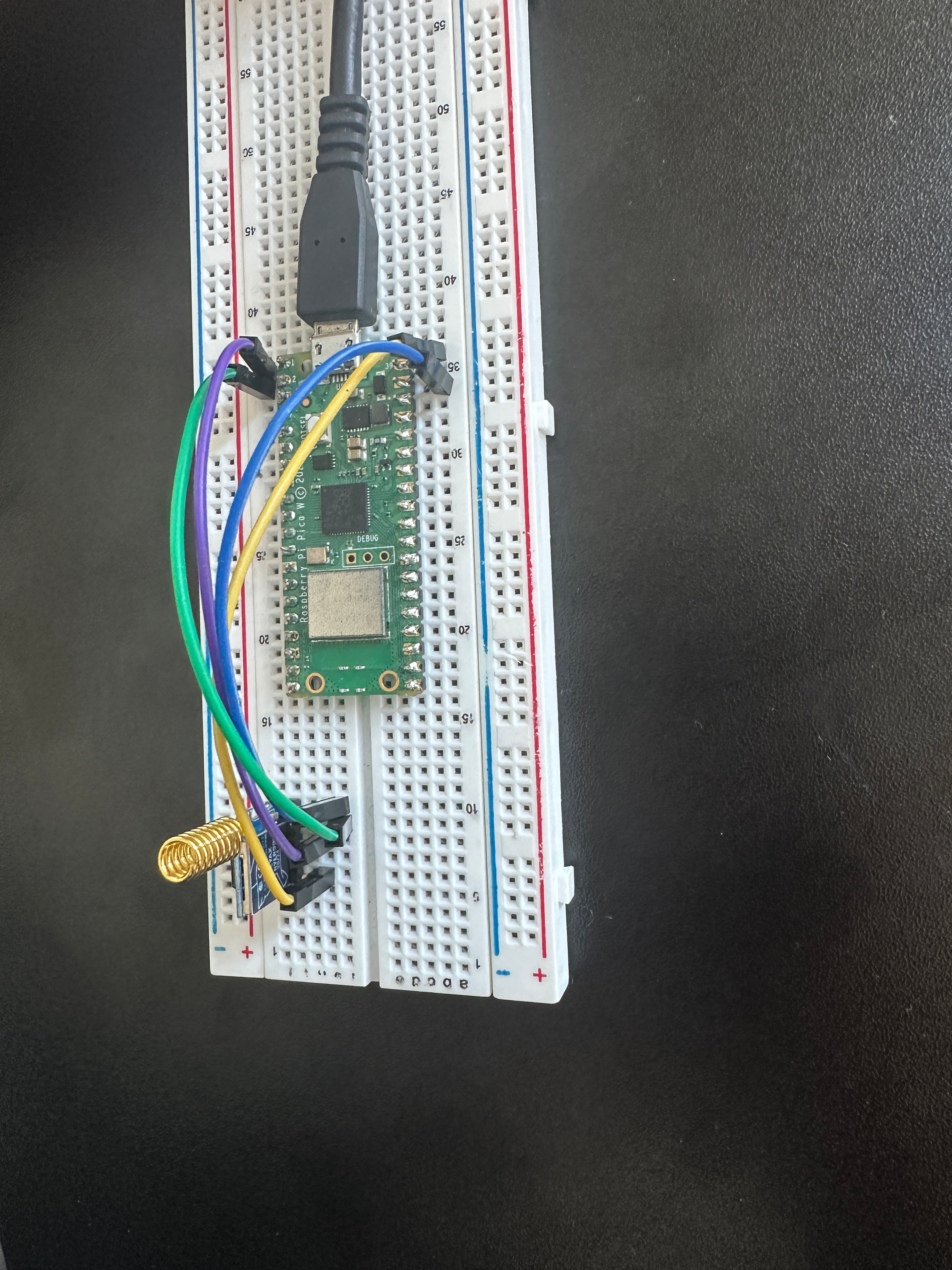
Expected result: Both Pico W boards are wired to their LoRa modules with TX and RX crossed, and the modules are powered from 3.3V and GND.
Step 3 - Program the sender Pico W
Goal: Configure the sender LoRa module with AT commands and transmit a message periodically.
What to do: Upload the following code to the Pico W you chose as the sender.
Code:
import machine
import utime

uart = machine.UART(0, baudrate=115200, tx=machine.Pin(0), rx=machine.Pin(1))

def send_command(command):
    if isinstance(command, str):
        command = command.encode('ascii')
    uart.write(command + b"\r\n")
    utime.sleep(0.5)
    while uart.any():
        response = uart.read()
        if response:
            print("Response:", response.decode('utf-8', 'ignore'))

def initialize_lora():
    send_command("AT")
    send_command("AT+ADDRESS=1")
    send_command("AT+NETWORKID=5")
    send_command("AT+BAND=915000000")

def send_message():
    message = "Hello Receiver"
    command = f"AT+SEND=2,{len(message)},{message}"
    send_command(command)

initialize_lora()
while True:
    send_message()
    utime.sleep(5)
Expected result: In the sender serial console, you should see responses from the LoRa module after each AT command and after each send.
Step 4 - Program the receiver Pico W
Goal: Configure the receiver LoRa module with AT commands and print received messages to the console.
What to do: Upload the following code to the Pico W you chose as the receiver.
Code:
import machine
import utime

uart = machine.UART(0, baudrate=115200, tx=machine.Pin(0), rx=machine.Pin(1))

def send_command(command):
    if isinstance(command, str):
        command = command.encode('ascii')
    uart.write(command + b"\r\n")
    utime.sleep(0.5)
    while uart.any():
        response = uart.read()
        print("Response:", response.decode('utf-8', 'ignore'))

def initialize_lora():
    send_command("AT")
    send_command("AT+ADDRESS=2")
    send_command("AT+NETWORKID=5")
    send_command("AT+BAND=915000000")

def listen_for_messages():
    buffer = b""
    while True:
        if uart.any():
            data = uart.read()
            buffer += data
            if b"\r\n" in buffer:
                lines = buffer.split(b"\r\n")
                buffer = lines.pop()
                for line in lines:
                    line_str = line.decode('utf-8', 'ignore').strip()
                    if line_str.startswith("+RCV="):
                        parts = line_str.split(",")
                        address = parts[0].split('=')[1]
                        message = parts[2]
                        print(f"Received message from address {address}: {message}")

initialize_lora()
listen_for_messages()
Expected result: In the receiver serial console, you should see LoRa module responses and printed lines when a message is received.
Step 5 - Power both boards and verify communication
Goal: Confirm the sender transmits and the receiver prints the received payload.
What to do:
- Power on both Pico W boards.
- Leave the sender running; it transmits periodically.
- Watch the receiver console for received message output.
Expected result: The receiver console displays messages such as: Received message from address 1: Hello Receiver.
Conclusion
You built a basic LoRa sender-receiver communication system using two Raspberry Pi Pico W boards and UART-based LoRa modules. This prototype demonstrates long-range, low-power messaging that is useful for IoT projects like monitoring and tracking.
Want the parts for this build? Grab what you need from ShillehTek.com. If you want help customizing this project for your hardware, range requirements, or a real product, check out our IoT consulting services.


.png?v=25000753014097803521779072085)

.png?v=68677308723310773341779072085)


