

Project Overview
Control an ESP32 Output Over Bluetooth from Your Phone: Use an ESP32 and its built-in Bluetooth Classic Serial (SPP) to switch an LED or relay from your phone using simple text commands in a serial terminal app. Pair your phone with the ESP32 and send commands like led on, led off, toggle, and status with feedback messages sent back to the phone.
- Time: ~25 minutes
- Skill level: Beginner
- What you will build: A Bluetooth command interface ("led on", "led off", "toggle", "status") with feedback messages sent back to the phone.

Parts List
From ShillehTek
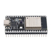
- ESP32 38-Pin Dev Board (CP2102, USB-C) - the original ESP32 has Bluetooth Classic built in
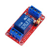
- 1-Channel 5V Relay Module - to switch a real load once the LED works
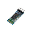
- HC-05 Bluetooth Module - gives a plain Arduino the same trick (see Step 5)
- 400-Point Breadboard
- Dupont Jumper Wires
External
- An Android phone with a Bluetooth serial terminal app (e.g. "Serial Bluetooth Terminal")
- LED + 220Ω resistor if you want an external indicator
Note: This project uses Bluetooth Classic (SPP), which is only on the original ESP32 chip. ESP32-C3, S3, and C6 boards are BLE-only and need a different library. iPhones do not support SPP either, so use an Android phone or a laptop for the terminal.
Step-by-Step Guide
Step 1 - Wire an Output
Goal: Something to switch.
What to do: Start with the onboard LED on GPIO 2. For an external LED: GPIO 2 → 220Ω → LED → GND. For a relay: GPIO 2 → IN, VCC → 5V (VIN pin), GND → GND.

Expected result: The hardware is done; the rest is software.
Step 2 - Install the Terminal App
Goal: A way to type to the ESP32.
What to do: Install a Bluetooth serial terminal app on your Android phone. Any app that speaks SPP works; the one linked above lets you define macro buttons, which you will use in Step 4.
Expected result: An app ready to pair.
Step 3 - The Sketch
Goal: Create a Bluetooth Serial command parser that controls GPIO 2 and replies back to the phone.
Code:
#include "BluetoothSerial.h"

BluetoothSerial SerialBT;
const int LED = 2;
bool ledOn = false;

void setLed(bool on) {
  ledOn = on;
  digitalWrite(LED, on ? HIGH : LOW);
  SerialBT.println(on ? "LED is ON" : "LED is OFF");    // feedback to the phone
}

void setup() {
  Serial.begin(115200);
  pinMode(LED, OUTPUT);
  SerialBT.begin("ESP32test");                          // the name you'll pair with
  Serial.println("Pair with 'ESP32test', then open the terminal app");
}

void loop() {
  if (SerialBT.available()) {
    String cmd = SerialBT.readStringUntil('\n');
    cmd.trim(); cmd.toLowerCase();

    if      (cmd == "led on")  setLed(true);
    else if (cmd == "led off") setLed(false);
    else if (cmd == "toggle")  setLed(!ledOn);
    else if (cmd == "status")  SerialBT.println(ledOn ? "LED is ON" : "LED is OFF");
    else SerialBT.println("Commands: led on | led off | toggle | status");

    Serial.println("BT> " + cmd);                        // echo to USB for debugging
  }
}
What to do: Upload, then on the phone: Bluetooth settings → pair with "ESP32test" → open the terminal app → connect → type led on and send (the app should append a newline).
Expected result: The LED lights and "LED is ON" appears in the terminal. toggle flips it; anything else prints the help line.
Step 4 - Buttons Instead of Typing
Goal: A remote, not a keyboard.
What to do: Most terminal apps let you assign a text string to a macro button. Make three: "led on", "led off", "toggle". Now the phone screen is a three-button remote control.
Add more commands to the sketch ("fan on", "pump off") and more buttons, and you have a whole control panel.
Expected result: One-tap control from the phone.
Step 5 - The Arduino Version with HC-05
Goal: Same idea on a plain Uno or Nano.
What to do: Boards without radios get one with an HC-05 module: VCC → 5V, GND → GND, TXD → Arduino RX, RXD → Arduino TX through a 1k/2k voltage divider (the module's RX is 3.3 V).
Use SoftwareSerial at 9600 baud and the exact same command-parsing loop; the HC-05 simply hands you the bytes your phone sent.
Expected result: Bluetooth control on any Arduino in your drawer.
Conclusion
Bluetooth Serial removes the networking hurdles between you and your ESP32: pair once, send text, get text back. This command-parser pattern (read a line, trim it, compare, act, reply) is the same one you will use for Wi-Fi sockets, LoRa packets, and USB serial projects.
Want the exact parts used in this build? Grab them from ShillehTek.com. If you want help customizing this project or building something for your product, check out our IoT consulting services.
Credits
All photos and images in this tutorial are credited to ard12sgf1960 on Hackster.io. The original guide by ard12sgf1960 served as the reference for this ShillehTek version. We thank them for their excellent work in the maker community.




.png?v=25000753014097803521791168436)

.png?v=68677308723310773341791168436)


