

Project Overview
Arduino Nano TDS Water Quality Meter: Use an Arduino Nano with a Gravity-compatible analog TDS sensor module to measure total dissolved solids in water and display the result in PPM on an SSD1306 OLED.
This is a practical dip-and-read meter for comparing tap, borewell, filtered, or distilled water samples with live readings on the OLED and in the Serial Monitor.
- Time: ~1 hour
- Skill level: Beginner
- What you will build: A dip-and-read TDS meter with live PPM readings on a 128x64 OLED and the Serial Monitor.

Parts List
From ShillehTek
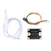
- Analog TDS Water Quality Sensor Module - provides the probe and the analog interface output.
- Arduino Nano V3.0 Pre-Soldered - reads the analog signal and drives the display (an Uno works identically).
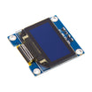
- SSD1306 0.96" I2C OLED Display (128x64) - shows the live PPM reading.
- 400-Point Breadboard - quick prototyping for the circuit.
- Dupont Jumper Wires - connects the Nano, sensor module, and OLED.
External
- Water samples to compare (tap, filtered, distilled, etc.)
- Optional: a custom PCB shield if you want a permanent handheld unit
Note: TDS guidelines for drinking water - under ~300 ppm is considered excellent; readings near zero (distilled) mean no dissolved minerals at all.
Step-by-Step Guide
Step 1 - What TDS Actually Measures
Goal: Understand the measurement before trusting it.
What to do: Total Dissolved Solids is the sum of everything dissolved in the water, including minerals, salts, and impurities. The measurement principle is simple: two electrodes, a voltage between them, and the conductivity of the water in between indicates how much is dissolved in it.

Expected result: You know what a PPM reading represents.
Step 2 - Meet the Gravity TDS Sensor
Goal: Know why a dedicated module beats bare electrodes.
What to do: The sensor board excites the probe with an AC signal, which helps prevent electrode polarization and improves repeatability. It runs from 3.3 to 5.5 V, outputs a 0 to 2.3 V analog signal, and measures 0 to 1000 ppm at ±10% F.S.


Expected result: Sensor operation and key specs are understood.
Step 3 - Gather Components and Wire It
Goal: Assemble the circuit.

What to do: Wire the TDS sensor module VCC to 5V, GND to GND, and analog out to A1. Wire the OLED on I2C: SDA to A4, SCL to A5, VCC to 5V, and GND to GND. Plug the probe into its connector on the interface board.


Expected result: Hardware is assembled and ready to program.
Step 4 - Upload the Code
Goal: Median-filter the readings and convert voltage to PPM.
What to do: Install Adafruit GFX and Adafruit SSD1306 from the Arduino IDE Library Manager. The sketch samples the sensor repeatedly, median-filters the noise, applies temperature compensation, and converts voltage to PPM using the standard Gravity cubic formula.
Code:
#include <Wire.h>
#include <Adafruit_GFX.h>
#include <Adafruit_SSD1306.h>

#define TdsSensorPin A1
#define VREF 5.0          // ADC reference voltage
#define SCOUNT 30         // samples for median filtering

Adafruit_SSD1306 display(128, 64, &Wire, -1);

int analogBuffer[SCOUNT];
int bufferIndex = 0;
float temperature = 25;   // compensation temperature
float tdsValue = 0;

void setup() {
  Serial.begin(115200);
  pinMode(TdsSensorPin, INPUT);
  display.begin(SSD1306_SWITCHCAPVCC, 0x3C);
  display.clearDisplay();
}

void loop() {
  // sample every 40 ms into the ring buffer
  analogBuffer[bufferIndex] = analogRead(TdsSensorPin);
  bufferIndex = (bufferIndex + 1) % SCOUNT;
  delay(40);

  // median-filtered average voltage
  float averageVoltage = getMedianNum(analogBuffer, SCOUNT) * VREF / 1024.0;

  // temperature compensation, then the Gravity voltage to ppm curve
  float compensation = 1.0 + 0.02 * (temperature - 25.0);
  float v = averageVoltage / compensation;
  tdsValue = (133.42 * v * v * v - 255.86 * v * v + 857.39 * v) * 0.5;

  display.clearDisplay();
  display.setTextSize(2);
  display.setTextColor(SSD1306_WHITE);
  display.setCursor(10, 20);
  display.print(tdsValue, 0);
  display.print(" ppm");
  display.display();
}
Expected result: The sketch compiles and uploads, and the OLED shows 0 ppm in air.
Step 5 - (Optional) Build It on a Shield
Goal: Go from breadboard to a handheld tool.
What to do: For a more permanent build, you can move the circuit to a custom Nano shield with onboard headers and dedicated sockets. Any PCB service can fabricate something similar from your own layout.


Expected result: A permanent home for the meter (optional).
Step 6 - Dip and Measure
Goal: Read real water samples.
What to do: Dip the probe into your sample and watch the PPM settle on the OLED and Serial Monitor. Out of water it reads zero. Give it a few seconds in liquid to stabilize, then compare tap vs. filtered vs. distilled water.


Probe care notes: do not use it in water above 55 C, and keep it away from the container edge since both can affect the reading. The probe head and cable are waterproof; the connector and interface board are not.

Expected result: Stable PPM readings that let you compare water quality across samples.
Conclusion
Using an Arduino Nano, a Gravity-compatible analog TDS sensor module, and an SSD1306 OLED, you built a useful dissolved-solids meter that displays live PPM readings. The AC-excited probe and median filtering help make the measurements more stable for everyday comparisons.
Want the exact parts used in this build? Grab them from ShillehTek.com. If you want help customizing this project or building something for your product, check out our IoT consulting services.
Credits
All photos and images in this tutorial are credited to Lithium ION on Hackster.io. The original guide by Lithium ION served as the reference for this ShillehTek version. We thank them for their excellent work in the maker community.





.png?v=25000753014097803521791168436)

.png?v=68677308723310773341791168436)


