

Project Overview
Arduino LED Pendulum Metronome: Build an Arduino Nano metronome using an SSD1306 0.96 inch I2C OLED, a KY-006 passive buzzer, and eight LEDs so the lights sweep like a pendulum, the buzzer clicks the beat with a 4/4 accent, and the OLED shows BPM and the Italian tempo marking.
A mechanical metronome is a swinging arm you can see across a room and a click you can hear over an instrument. This build recreates both with a Nano: eight LEDs in a row “swing” like the pendulum, a buzzer clicks at each end of the swing (louder on beat one of the bar), and a small OLED shows the tempo in BPM with its Italian marking. A potentiometer sets anything from a 40 BPM Largo to a 208 BPM Presto.
- Time: ~40 minutes
- Skill level: Beginner
- What you will build: A visual-plus-audible metronome with a 40 to 208 BPM knob, 4/4 accents, drift-free millis() timing and a live OLED readout.

Parts List
From ShillehTek
- Arduino Nano V3.0 Pre-Soldered - runs the LED sweep, BPM timing, OLED display, and buzzer accent.
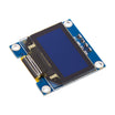
- 0.96" I2C OLED (SSD1306) - displays BPM, tempo marking, and beat count.
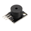
- KY-006 Passive Buzzer - provides the audible click with a higher accent on beat 1.
- Arduino Uno R3 Super Starter Kit - provides eight LEDs (two red, six green) and a potentiometer for tempo control.
- Resistor Kit - use one 470Ω resistor for the shared LED cathode return.
- 830-Point Breadboard - mounts the LEDs, resistor, and interconnects.
- Dupont Jumper Wires - connects the Nano to the LEDs, OLED, buzzer, and potentiometer.
External
- None
Note: One resistor for eight LEDs works here because only one LED is ever lit at a time. The cathodes all meet at a single 470Ω to ground. If you later want several LEDs on together, give each its own resistor.
Step-by-Step Guide
Step 1 - Wire the LED Row
Goal: An eight-LED pendulum.
What to do: Place eight LEDs in a line. Anodes (long legs) go to D2, D3, D4, D5, D6, D7, D8, D9 in order. Connect all cathodes to one breadboard row, then through a 470Ω resistor to GND. Use red LEDs at both ends (the beat positions) and green in the middle.

Expected result: A row that can light any single LED.
Step 2 - Wire OLED, Pot and Buzzer
Goal: Tempo control and readout.
What to do: Wire the OLED as SDA to A4, SCL to A5, VCC to 5V, and GND to GND. Wire the potentiometer ends to 5V and GND, and the wiper to A0. Wire the KY-006 buzzer module as S to D11 and minus to GND.
Expected result: All inputs and outputs in place.
Step 3 - The Sketch
Goal: Program the Nano to sweep LEDs, compute BPM timing, click accents, and update the OLED.
What to do: Install the Adafruit GFX and Adafruit SSD1306 libraries, then upload the sketch below. Turn the potentiometer to change the tempo.
Code:
#include <Adafruit_GFX.h>
#include <Adafruit_SSD1306.h>
Adafruit_SSD1306 oled(128, 64, &Wire, -1);

const int LED[8] = {2, 3, 4, 5, 6, 7, 8, 9};
const int POT = A0, BUZZ = 11;
const int BEATS_PER_BAR = 4;

int pos = 0, dir = 1, beat = 0, bpm = 120;
unsigned long nextStep = 0;

const char* marking(int b) {
  if (b < 60)  return "Largo";
  if (b < 76)  return "Adagio";
  if (b < 108) return "Andante";
  if (b < 120) return "Moderato";
  if (b < 156) return "Allegro";
  if (b < 176) return "Vivace";
  return "Presto";
}

void showBpm() {
  oled.clearDisplay();
  oled.setTextSize(3); oled.setCursor(10, 8);  oled.print(bpm);
  oled.setTextSize(2); oled.setCursor(76, 14); oled.print("BPM");
  oled.setTextSize(1); oled.setCursor(10, 44); oled.print(marking(bpm));
  oled.setCursor(10, 54); oled.print("4/4   beat "); oled.print(beat + 1);
  oled.display();
}

int readBpm() {                                   // averaged, so the number doesn't jitter
  long s = 0; for (int i = 0; i < 8; i++) s += analogRead(POT);
  return map(s / 8, 0, 1023, 40, 208);
}

void setup() {
  for (int i = 0; i < 8; i++) pinMode(LED[i], OUTPUT);
  oled.begin(SSD1306_SWITCHCAPVCC, 0x3C);
  oled.setTextColor(SSD1306_WHITE);
  digitalWrite(LED[0], HIGH);
  showBpm();
  nextStep = millis();
}

void loop() {
  int b = readBpm();
  if (abs(b - bpm) >= 2) { bpm = b; showBpm(); }  // small dead band = no flicker

  unsigned long stepMs = 60000UL / bpm / 7;       // one beat = 7 steps, end to end
  if ((long)(millis() - nextStep) >= 0) {
    nextStep += stepMs;                           // schedule from the last due time: no drift
    digitalWrite(LED[pos], LOW);
    pos += dir;
    digitalWrite(LED[pos], HIGH);
    if (pos == 0 || pos == 7) {                   // an end of the swing = a beat
      dir = -dir;
      tone(BUZZ, beat == 0 ? 1500 : 1000, 30);    // higher click on beat 1
      beat = (beat + 1) % BEATS_PER_BAR;
      showBpm();
    }
  }
}
Expected result: The lit LED sweeps left, right, left like a pendulum. Each time it reaches a red end LED the buzzer clicks, with a higher click every fourth beat, and the OLED shows the tempo, its name (for example, “Allegro”) and the beat number. Turning the pot changes the speed immediately.
Step 4 - Why the Timing Is Trustworthy
Goal: A metronome that stays in time.
What to do: Two details matter. Timing is scheduled (nextStep += stepMs) rather than measured from “now”, so a slow OLED redraw cannot push every following beat late because the sketch catches up. Also, the OLED only redraws on a beat or a tempo change, not on every LED step. Check it against a phone metronome app at 120 BPM: they should stay locked for minutes.
Expected result: No drift, which is the property a metronome exists for.
Step 5 - Make It a Practice Tool
Goal: Outline common extensions musicians ask for.
What to do: Add a button to cycle time signatures (3/4, 4/4, 6/8 by changing BEATS_PER_BAR). Add a “tap tempo” button by measuring the gap between taps and setting bpm from it. Mute the buzzer with a switch for silent visual practice. Store the last tempo in EEPROM. Run it from a TP4056 and a cell in a small case for portable use.
Expected result: A metronome you would rather use than an app.
Conclusion
This Arduino Nano LED pendulum metronome uses eight LEDs for a clear visual beat, a KY-006 buzzer for audible accents, and an SSD1306 OLED to show BPM and tempo marking. The scheduled timing approach keeps the beat stable, even when the display updates.
Want the exact parts used in this build? Grab them from ShillehTek.com. If you want help customizing this project or building something for your product, check out our IoT consulting services.
Credits
All photos and images in this tutorial are credited to Mirko Pavleski (mircemk) on Hackster.io. The original guide by Mirko Pavleski served as the reference for this ShillehTek version. We thank them for their excellent work in the maker community.







.png?v=25000753014097803521791168436)

.png?v=68677308723310773341791168436)


