

Project Overview
Arduino Nano + MAX485 RS485 module Modbus RTU slave: In this guide, you build a Modbus RTU slave device on an Arduino Nano using a MAX485 TTL to RS485 converter module, then read and write its registers from a PC acting as the Modbus master, including toggling an LED by writing register 400007.
Modbus is a common protocol in industrial equipment like PLCs, meters, VFDs, and sensors, often used as Modbus RTU over an RS485 twisted pair. An Arduino can act as a Modbus slave once it has an RS485 interface.
- Time: 1-2 hours
- Skill level: Intermediate
- What you will build: A Modbus RTU slave device you can poll and control from a Modbus master.

Parts List
From ShillehTek
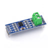
- MAX485 TTL to RS485 Converter Module - adds an RS485 interface (A/B bus) to the Arduino UART
- Arduino Nano V3 - UNO-compatible Arduino for the Modbus slave
- Resistor Kit - 220 ohm for the LED, 10K for the button pull-down
- Tactile Button Kit, breadboard, and jumper wires - for the LED/button demo I/O wiring
External
- USB-RS485 adapter for the PC master side
- Red LED
- Twisted-pair wire for the A/B RS485 bus
- Modbustester (free Windows utility)
- SimpleModbus library: github.com/angeloc/simplemodbusng
Note: RS485 is a differential bus with two shared data lines (A and B). Use twisted pair for long runs and terminate only at the two physical ends of the bus.
Step-by-Step Guide
Step 1 - Gather the hardware and software
Goal: Get both the Modbus slave (Arduino) and the Modbus master (PC) ready.
What to do: Use an Arduino plus an RS485 interface as the slave. Use a PC with a USB-RS485 adapter as the master. Install the Arduino IDE, the SimpleModbus library, and Modbustester on the PC.

Expected result: You have a clear master device (PC) and slave device (Arduino) and the required software tools.
Step 2 - Wire the RS485 bus
Goal: Connect the slave to the RS485 A/B pair correctly.
What to do: Connect the interface A terminal to the bus A wire and B to B. On a MAX485 module, wire the TTL side as follows: DI to Arduino TX, RO to Arduino RX, DE and RE tied together to a control pin (or to auto-direction circuitry), VCC to 5V, and GND to GND.

Expected result: The Arduino RS485 interface is physically connected to the same A/B bus as the PC USB-RS485 adapter.
Step 3 - Add the demo LED and button (optional)
Goal: Add a visible output and a readable input to test Modbus reads and writes.
What to do: Wire a red LED through a 220 ohm resistor to an Arduino output pin. Wire a push button with a 10K pull-down resistor to an Arduino input pin. These I/O points will be exposed through Modbus registers.


Expected result: You have one output (LED) and one input (button) to verify control and monitoring over RS485.
Step 4 - Configure the interface (shield users)
Goal: Set UART routing and termination correctly for reliable RS485 communication.
What to do: If you are using a full RS485 shield: set its DIP banks per the photos (bank 1: OFF-ON-ON-OFF; bank 2: OFF-OFF-ON-ON; bank 3: all OFF except switch 1, which is ON only if the shield is at a physical end of the bus, enabling the 120 ohm terminating resistor). Set the supply jumper to 5V for an UNO-class board, route UART pins 0/1 to the RS485 side, and leave RX/TX direction control on automatic. If you are using a MAX485 module instead of a shield, the same concepts apply: 5V supply, correct UART wiring, and termination only at the ends of the bus.


Expected result: The interface is configured properly, with termination enabled only when the device is at a bus end.
Step 5 - Set up the PC master
Goal: Configure a Modbus master to communicate with the Arduino slave.
What to do: Plug in the USB-RS485 adapter. Unzip and open Modbustester, select the adapter COM port, and match the serial settings shown in the screenshot.

Expected result: Your PC is ready to send Modbus RTU read and write requests over RS485.
Step 6 - Flash the slave sketch
Goal: Program the Arduino with a Modbus RTU slave register map.
What to do: Install the SimpleModbus library, then load the SimpleModbusSlave example for your board (UNO version for UNO/Nano) from the original project downloads and upload it. The sketch maps holding registers as follows: the six ADC ports are in registers 400001 to 400006, the LED is at 400007, and the button state is at 400008.
Expected result: The Arduino is serving Modbus registers on the RS485 bus.
Step 7 - Read and write registers
Goal: Verify end-to-end Modbus communication between the PC master and Arduino slave.
What to do: In Modbustester, click Read to fetch eight registers. You should see analog values in 400001 to 400006 and the button state in 400008 (press the button and read again). Then write a 1 to address 400007 to turn the LED on, and write 0 to turn it off.

Expected result: The PC can read analog and button registers and can control the Arduino LED by writing register 400007.
Conclusion
You built a Modbus RTU slave using an Arduino with an RS485 interface (MAX485), exposing ADC inputs and a button as readable registers and controlling an LED by writing holding register 400007 from a PC Modbus master.
Want the exact parts used in this build? Grab them from ShillehTek.com. If you want help customizing this project or building something for your product, check out our IoT consulting services.






.png?v=25000753014097803521791168436)

.png?v=68677308723310773341791168436)


