

Project Overview
DIY Arduino Nano LCD1602 Autorange Capacitance Meter: Build an Arduino Nano-based capacitance meter with an LCD1602 (I2C) readout that measures capacitors from about 10 pF up to 10,000 µF by timing an RC charge curve and auto-selecting the best range.
Most multimeters cannot measure capacitance, but an Arduino can by using timing. Charge the unknown capacitor through a known resistor, measure how long it takes to reach 63.2% of the supply, and use C = t / R. With two resistors and a bit of logic, the meter automatically ranges itself from picofarads to thousands of microfarads.
- Time: ~1 hour
- Skill level: Intermediate
- What you will build: A bench capacitance meter with LCD readout for identifying unlabeled capacitors.

Parts List
From ShillehTek
- Arduino Nano V3.0 Pre-Soldered - runs the timing and range-selection logic.
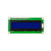
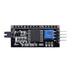
- LCD1602 Display + PCF8574 I2C backpack - displays capacitance readings over I2C.
- Resistor Kit - provides the 1kΩ and 1MΩ charge resistors and 220Ω discharge resistor.
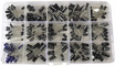
- Electrolytic Capacitor Kit - known values to verify readings.
- 400-Point Breadboard - prototyping the RC test circuit.
- Dupont Jumper Wires - quick wiring between the Nano, resistors, and LCD.
External
- Two test leads or a pair of header sockets - for the capacitor under test connection.
Note: An RC circuit reaches 63.2% of its final voltage after exactly one time constant, τ = R × C. On a 10-bit ADC, 63.2% of 1023 is 647, so you time the climb to 647 and divide by R.
Step-by-Step Guide
Step 1 - Wire the Test Circuit
Goal: Build two charge paths with one sense node for timing.
What to do: Connect the capacitor under test with its negative lead to GND and its positive lead to A0. From A0, run a 1kΩ resistor to D7 (fast charge for large capacitors) and a 1MΩ resistor to D8 (slow charge for small capacitors). Add a 220Ω resistor from A0 to D9 to discharge between readings. Connect the I2C LCD to A4 (SDA) and A5 (SCL).

Expected result: A test socket wired so the Arduino can time the capacitor charging curve.
Step 2 - Time the Charge
Goal: Measure one time constant (to 63.2% of final voltage).
What to do: Discharge the capacitor fully, set the selected charge pin HIGH, start a micros() stopwatch, and wait for A0 to cross 647 (63.2% of a 10-bit ADC full scale). The elapsed microseconds divided by the resistance gives capacitance in farads; scale the result for display (nF or µF).
Expected result: One raw capacitance measurement from timing to the 63.2% threshold.
Step 3 - Autorange and Display
Goal: Automatically switch between the 1kΩ and 1MΩ ranges and show the result on the LCD.
Code:
#include <LiquidCrystal_I2C.h>
LiquidCrystal_I2C lcd(0x27, 16, 2);

const int SENSE = A0, CHG_1K = 7, CHG_1M = 8, DISCH = 9;

void discharge() {
  pinMode(CHG_1K, INPUT); pinMode(CHG_1M, INPUT);
  pinMode(DISCH, OUTPUT); digitalWrite(DISCH, LOW);
  while (analogRead(SENSE) > 0);
  pinMode(DISCH, INPUT);
}

// returns microseconds to reach 63.2% through the given pin
unsigned long timeConstant(int pin, unsigned long timeoutUs) {
  pinMode(pin, OUTPUT); digitalWrite(pin, HIGH);
  unsigned long t0 = micros();
  while (analogRead(SENSE) < 647) {
    if (micros() - t0 > timeoutUs) { pinMode(pin, INPUT); return 0; }
  }
  unsigned long t = micros() - t0;
  pinMode(pin, INPUT);
  return t;
}

void setup() { lcd.init(); lcd.backlight(); }

void loop() {
  discharge();
  unsigned long t = timeConstant(CHG_1K, 1000000UL);   // try fast range first
  float value; const char* unit;

  if (t > 0) {                     // big capacitor: C = t / 1k  (uF)
    value = t / 1000.0; unit = "uF";
  } else {                         // tiny capacitor: use 1M  (nF)
    discharge();
    t = timeConstant(CHG_1M, 3000000UL);
    value = t / 1000.0; unit = "nF";
  }

  lcd.setCursor(0, 0); lcd.print("Capacitance:    ");
  lcd.setCursor(0, 1);
  if (t == 0) lcd.print("-- no cap --    ");
  else { lcd.print(value, 2); lcd.print(" "); lcd.print(unit); lcd.print("       "); }
  delay(800);
}
What to do: Upload the sketch, plug a 100 µF electrolytic into the test socket, and read the value. Then try a 100 nF ceramic capacitor. The meter should switch to the 1MΩ path automatically for small values.
Expected result: Readings within about 10% of marked values across a wide range, and the unit switching between nF and µF.
Step 4 - Calibrate and Trust It
Goal: Improve accuracy by correcting the dominant error sources.
What to do: Resistor tolerance is the main error. Measure your actual 1kΩ and 1MΩ resistors with a multimeter and use those exact values in the math. Stray capacitance of the breadboard (often around 20 to 50 pF) sets the lower measurement floor; subtract a no-cap reading if you want better results at the picofarad end.
Expected result: A capacitance meter you can use to identify unknown capacitors with more consistent readings.
Conclusion
This Arduino Nano capacitance meter uses the RC time constant (τ = R × C) and micros() timing to produce an autoranging LCD1602 readout across very small and very large capacitors. It is a practical bench tool and a solid exercise in timing, range switching, and understanding measurement error.
Want the exact parts used in this build? Grab them from ShillehTek.com. If you want help customizing this project or building something for your product, check out our IoT consulting services.
Credits
All photos and images in this tutorial are credited to Mirko Pavleski on Hackster.io. The original guide by Mirko Pavleski served as the reference for this ShillehTek version. We thank him for his excellent work in the maker community.






.png?v=25000753014097803521791168436)

.png?v=68677308723310773341791168436)