

Project Overview
Arduino Uno or Nano + AMG8833 thermal sensor: Build an 8x8 thermal camera that streams a live false-color heat map to your Windows PC using a simple 4-wire I2C hookup and an Arduino sketch.
This project uses Panasonic's Grid-EYE infrared array (AMG8833) and a free Windows VirtualPanel app for live viewing. Even though the sensor is only 64 pixels, the display app can interpolate the data into smoother, higher-resolution-looking images.
- Time: ~1 hour
- Skill level: Beginner
- What you will build: A handheld 8x8 thermal camera that streams a false-color heat map to your PC, with interpolation modes that upscale the image well beyond the native 64 pixels.

Parts List
From ShillehTek
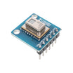
- AMG8833 Pre-Soldered 8x8 IR Thermal Imaging Camera Sensor - the thermal sensor module used for the 8x8 temperature grid.
- Super Starter Kit for Arduino Uno R3 (or any Uno R3) - the main microcontroller platform for the build.
- Arduino Nano V3.0 Pre-Soldered CH340G - a smaller alternative board for a compact handheld version.
- 120pcs 20cm Dupont Jumper Wires - for power and I2C wiring.
- 400-Point Small Solderless Breadboard - quick prototyping for the initial build.
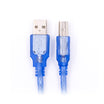
- USB 2.0 A-B Cable (for the Uno) - USB connection for power and serial data.
External
- Windows PC (the VirtualPanel display app is Windows-based)
- Optional: small perfboard and a mini tripod if you want a handheld unit
Note: The AMG8833 module includes an onboard regulator and level shifting, so it works with 3.3V or 5V logic and is compatible with Arduino Uno and Nano.
Step-by-Step Guide
Step 1 - Get to Know the AMG8833 Grid-EYE
Goal: Understand what the sensor can (and cannot) do before you wire it.
What to do: The AMG8833 is Panasonic's low-cost infrared array: 64 thermopile pixels arranged 8x8, read out over I2C. That resolution sounds small, but it is enough for spotting warm electronics, drafts, pets, and people. The module format adds a regulator and level shifters, so both 3.3V and 5V boards can drive it directly.
This project is designed to run on the ATmega328's limited RAM by sending only pixel data to the PC. The PC app handles the rendering.
Expected result: You know the sensor outputs an 8x8 grid of temperatures up to 10 frames per second over I2C address 0x69 (or 0x68).
Step 2 - Wire the Sensor (4 Wires)
Goal: Connect the AMG8833 to your board's I2C bus.
What to do: Only four jumpers are needed. For an Arduino Uno: VIN to 5V, GND to GND, SDA to A4, and SCL to A5.

For a Nano build, use the same I2C pins (A4/A5), which makes it easy to move the build to perfboard later.

Expected result: The sensor module is powered and connected to the I2C bus.
Step 3 - Install the Libraries
Goal: Install an AMG8833 driver and the VirtualPanel UI library.
What to do: In the Arduino IDE Library Manager, install the Melopero AMG8833 library. Then grab the VirtualPanel library and thermal-camera sketch from the project's GitHub releases page. Use the quick sanity-check sketch below to confirm your sensor responds.
Code:
#include <Wire.h>
#include <Melopero_AMG8833.h>

Melopero_AMG8833 sensor;

void setup() {
  Serial.begin(115200);
  Wire.begin();
  sensor.initI2C();
  sensor.resetFlagsAndSettings();
  sensor.setFPSMode(FPS_MODE::FPS_10);
}

void loop() {
  sensor.updatePixelMatrix();
  for (byte r = 0; r < 8; r++) {
    for (byte c = 0; c < 8; c++) {
      Serial.print(sensor.pixelMatrix[r][c], 1);
      Serial.print(" ");
    }
    Serial.println();
  }
  Serial.println();
  delay(500);
}
Expected result: The Serial Monitor prints an 8x8 grid of temperatures. Wave your hand over the sensor and watch the numbers change.
Step 4 - Flash the Thermal Camera Sketch
Goal: Load the full camera firmware.
What to do: Download the AMG8833-Thermal-Camera sketch from the project GitHub repository (check the releases page for the packaged download) and upload it to your Uno or Nano.
This design keeps the Arduino workload light by sending pixel data over USB while the PC performs the rendering.
Expected result: The sketch compiles and uploads with no errors.
Step 5 - Run VirtualPanel and Start Imaging
Goal: Display live thermal video on your PC.
What to do: Launch VirtualPanel on Windows, select your board's COM port, and open the camera panel. Use the UI controls to change palette selection, temperature range, interpolation level, and image capture options.

Expected result: A live false-color heat map. Switch interpolation modes to smooth the native 8x8 frame into 1064- or 2409-pixel views.
Step 6 - (Optional) Build the Handheld Unit
Goal: Make the build portable and easier to aim.
What to do: Start on a breadboard, then move the Nano and sensor to a small perfboard chassis. Mounting the board on a mini tripod can make aiming more comfortable. More build details are available in the project wiki.
Expected result: A pocket-size thermal camera you can point at warm objects.
Conclusion
You built an Arduino Uno or Nano thermal camera using the AMG8833 Grid-EYE sensor, streaming an 8x8 temperature grid to a Windows PC for a live false-color heat map with interpolation. By pushing rendering to the PC, the ATmega328 can still deliver usable thermal imaging over a single USB cable.
Photo and reference credit: JaapDanielse on Hackster.io and the linked GitHub project.
Want the exact parts used in this build? Grab them from ShillehTek.com. If you want help customizing this project or building something for your product, check out our IoT consulting services.






.png?v=25000753014097803521791168436)

.png?v=68677308723310773341791168436)


