
ADS1115 Pre-Soldered ADC Analog to Digital Converter Module for Arduino & Raspberry Pi
SKU KR-EZ4W-0150
16-bit I2C ADC module that gives Arduino and Raspberry Pi precise extra analog inputs for sensors and voltage monitoring.
Bulk eligible
Mix any Bulk eligible products — discount applies to your total quantity across the cart.| Buy 5+ | $9.27 each | Save 5% |
| Buy 10+ | $8.78 each | Save 10% |
- Free Ground Shipping U.S. orders $35+
- Ships from USA Domestic fulfillment
- 30-day returns Free defect replacement
- 7-day support Fast email replies
 ADS1115 Pre-Soldered ADC Analog to Digital Converter Module for Arduino & Raspberry Pi
★★★★★
(30)
$9.75
This item
ADS1115 Pre-Soldered ADC Analog to Digital Converter Module for Arduino & Raspberry Pi
★★★★★
(30)
$9.75
This item
Products related to this item
Overview
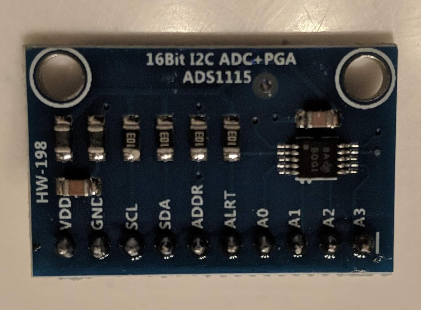
Product Overview
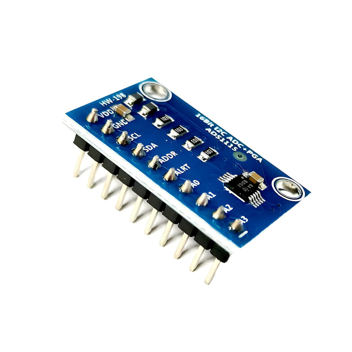
The ShillehTek ADS1115 ADC Module adds high-quality analog input capability to Arduino, Raspberry Pi, and other microcontroller projects by converting analog voltages into precise digital readings. It is a 16-bit analog-to-digital converter that communicates over I2C, making it easy to wire and great for reading sensors that output analog signals like potentiometers, light sensors, force sensors, gas sensors, and battery or solar voltage monitors. Use it when your board does not have enough analog pins, when you want higher resolution than a typical built-in ADC, or when you need stable measurements for data logging and IoT dashboards.
Questions & answers
Frequently asked questions
Have other questions?
Chat with our US-based team — we usually reply fast.
What's included
Features & Specs
Reference
Documents
Full Product Manual ADS1115, 4 Channel, I2C, IIC, Analog-to-Digital, ADC, PGA, 16 Bit, 16 Byte Converter In-depth setup guide with wiring, code examples, and troubleshooting.Learn
Related Tutorials

Raspberry Pi ADS1115: Read MQ-135 Analog Voltage

Arduino ADS1115: 16-bit Precision Analog Reads

ESP32 ADS1115: Monitor 4 Soil Sensors via Wi-Fi
Watch
Related Videos
Verified buyers
Customer Reviews


ADS1115 Pre-Soldered ADC Analog to Digital Converter Module for Arduino & Raspberry Pi