Overview
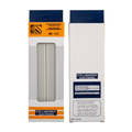
This 3-pack of 5x7cm single-sided copper prototype PCBs is the bridge between a messy breadboard and a finished, soldered project. Once you've proven a circuit works on a breadboard, transfer it to one of these boards and you get a permanent, durable version you can screw into an enclosure or tuck inside a project box.
Each board has a full grid of 2.54mm (0.1") through-holes — the same pitch as every Arduino, ESP32, Pico, Raspberry Pi HAT, and sensor breakout — so you can drop in IC sockets, headers, resistors, capacitors, modules, and wiring without drilling or re-pitching anything. The copper pad side faces down, and components go in from the top.
At a Glance
Hole Count
24 x 18 (432 Pads)
Layers
Single-Sided Copper
Board Material
FR-4 Fiberglass
Specifications
| Parameter |
Value |
| Board Dimensions |
50mm x 70mm (5 x 7 cm) |
| Board Thickness |
~1.6mm |
| Hole Pitch |
2.54mm (0.1") on a regular grid |
| Hole Diameter |
~1.0mm |
| Hole Count |
24 columns × 18 rows (432 pads) |
| Board Material |
FR-4 fiberglass epoxy |
| Copper Side |
Single-sided, 1oz/ft² copper with solder-mask around pads |
| Silkscreen |
None (plain copper on bottom, bare FR-4 on top) |
| Mounting Holes |
4 corner holes, 3mm (M3) compatible |
| Pieces Per Pack |
3 boards |
| Operating Temperature |
-40°C to +105°C |
How to Use
Plan your layout before you solder. Place components on the top (non-copper) side, with leads poking through to the copper side. For ICs, use a socket so the chip is removable. For connected pads, bridge them with a drop of solder between adjacent pads, or route with thin insulated wire on the copper side and solder at each pad.
The four corner holes are M3-sized, so you can mount the board to a 3D-printed base, project enclosure, or standoff kit without extra hardware. Trim long component leads with flush cutters after soldering for a clean finish.
Tip: Prototype your circuit on a breadboard first. Once it works, transfer component positions one at a time to the PCB — a "mirror image" transfer so the layout matches what you had on the breadboard.
Great for: ESP32/Pico/Arduino add-on shields, sensor aggregator boards, pull-up resistor networks, LED matrices, small audio circuits, level shifters, and any one-off circuit you want to keep running beyond the prototype stage.
No silkscreen, no drill guide: These are plain universal boards — no printed labels, component outlines, or pre-defined traces. You'll need to plan your own layout on paper or grid software before you start soldering.
Frequently Asked Questions
Will through-hole DIP chips, headers, and modules fit these holes?
Yes. The 2.54mm pitch is the universal standard for DIP ICs, IC sockets, 2.54mm pin headers, screw terminals, relays, trimpots, LEDs, electrolytic caps, resistors, and most dev modules. If it fits a breadboard, it fits this board.
How do I connect two pads that aren't adjacent?
Two options: run a thin piece of insulated wire (28-30 AWG) on the copper side between the two pads, or form a longer "solder bridge" by dragging molten solder across a row of empty pads. The wire method is cleaner for longer runs.
Can I cut these boards to a smaller size?
Yes, but use a scoring-and-snap technique or a fine-toothed saw — FR-4 is glass fiber reinforced and will dull cheap cutters. Score both sides along a row of holes with a utility knife or PCB cutter, then snap along the score line.
Are these single-sided or double-sided?
Single-sided. Copper pads are on one side only; the other side is bare FR-4 where you place components. For double-sided prototyping, look for boards explicitly labeled "double-sided" — they're a different product.
What soldering iron works best?
A 25-40W iron with a fine chisel or conical tip at 320-360°C is ideal. The pads are standard-sized — nothing special about soldering these boards. Use lead-free solder with a rosin core or standard 60/40 with a flux pen for trickier joints.
Can I mount this inside an enclosure?
Yes — each board has four M3-compatible corner mounting holes. Use M3 standoffs, bolts, or nylon spacers to raise the board off the enclosure surface and leave room for solder joints underneath.
Related Tutorials