

Project Overview
Pan-Tilt Servo Control with Raspberry Pi: Build a two-axis camera platform using a Raspberry Pi and two SG90 or MG90S micro servos, then control pan (left/right) and tilt (up/down) from Python using GPIO software PWM. This is the positioning core behind camera rigs, sensor turrets, and face-tracking projects.
- Time: 1 to 2 hours
- Skill level: Beginner to Intermediate
-
What you will build: A fully assembled pan-tilt head you can point anywhere with one Python function call:
setServoAngle(servo, angle).

Parts List
From ShillehTek
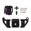
- Pan-Tilt Servo Bracket Kit for SG90 & MG90S Micro Servos - the mechanical frame for the two-axis build
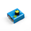
- RC Servo Tester & CCPM Checker - verify both servos sweep cleanly before mounting
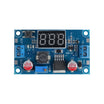
- LM2596 Adjustable Step-Down Converter - provides a stable external 5V rail for the servos
- Dupont Jumper Wires - easy GPIO and power connections
- 400-Point Breadboard - quick prototyping for power distribution and signal wiring
External
- Raspberry Pi (any model with GPIO - the original build used a Pi 3)
- 2 x SG90 or MG90S micro servos
- Optional: 2 x 1Ω resistors (GPIO signal protection) and a Pi camera to mount
Note: Do not power servos from the Pi's 5V pin. Two SG90s under load can brown out the Pi. Power them from their own 5V supply and tie the grounds together.
Step-by-Step Guide
Step 1 - How servo PWM works
Goal: Understand the control signal before writing code.
What to do: Hobby servos listen for a 50 Hz pulse train (20 ms period) and read the pulse width as a position command. Expressed as duty cycle, the usable band is small: roughly 3% duty = 0 b0, 8% = 90 b0, and 13% = 180 b0. Everything in this project reduces to generating the right duty cycle on a GPIO pin.

Expected result: You can predict what any duty cycle will do to the servo horn.
Step 2 - Wire the servos to the Raspberry Pi
Goal: Connect two servos safely.
What to do: Tilt servo signal goes to GPIO 17, and pan servo signal goes to GPIO 27 (a 1Ω resistor in series on each signal line is cheap insurance). Both servo power leads go to your external 5V rail (set the LM2596 to 5.0V). Tie Pi ground, servo grounds, and supply ground together. Without the shared ground the PWM has no reference and the servos will jitter or ignore commands.

Expected result: Both servos are wired, powered, and referenced correctly.
Step 3 - Calibrate each servo
Goal: Confirm the duty-cycle-to-angle mapping on your specific servos.
What to do: Before assembling anything, command each servo to 3%, 8%, and 13% duty and watch where the horn lands (0 b0, 90 b0, 180 b0). Cheap servos vary a few percent, so nudge the values until 90 b0 is truly centered. This is also the moment the servo tester helps: sweep each servo standalone and reject any that stutter.

Expected result: Two calibrated servos with known end stops.
Step 4 - Assemble the pan-tilt bracket
Goal: Build the two-axis mechanism.
What to do: The bracket kit sandwiches one servo horizontally (pan axis) and one vertically (tilt axis). Center both servos at 90 b0 before screwing the horns down, so the mechanical middle matches the electrical middle. The brackets snap together around each servo body, and the horns bolt to the moving frames.


Expected result: A pan-tilt head that moves freely through both axes.
Step 5 - Drive it from Python
Goal: Point the head anywhere with one function.
What to do: Use a linear mapping from angle to duty cycle: dutyCycle = angle / 18 + 3 maps 0 to 180 b0 onto the 3% to 13% band. Keep commands inside 30 to 150 b0 so the bracket does not bind at the extremes.
Code:
from time import sleep
import RPi.GPIO as GPIO

GPIO.setmode(GPIO.BCM)
GPIO.setwarnings(False)

pan  = 27
tilt = 17

GPIO.setup(tilt, GPIO.OUT)
GPIO.setup(pan, GPIO.OUT)

def setServoAngle(servo, angle):
    assert 30 <= angle <= 150          # stay inside the mechanical sweet spot
    pwm = GPIO.PWM(servo, 50)          # 50 Hz servo frame
    pwm.start(8)                       # start near center
    dutyCycle = angle / 18. + 3.       # 0-180 deg  ->  3%-13% duty
    pwm.ChangeDutyCycle(dutyCycle)
    sleep(0.3)
    pwm.stop()

# point the head: pan 45 deg, tilt 120 deg
setServoAngle(pan, 45)
setServoAngle(tilt, 120)
GPIO.cleanup()
Expected result: The head snaps to any commanded position. If you run a nested sweep loop over both axes you will get the classic patrol motion.

Step 6 - Give it a job
Goal: Turn a moving bracket into a project.
What to do: Bolt on a Pi camera for a patrol cam or face tracker, mount an ultrasonic or time-of-flight sensor for a scanning rangefinder, or aim a laser pointer for a cat toy. Anything that benefits from pointing benefits from pan-tilt.
Expected result: A two-axis platform you can integrate into your next build.
Conclusion
Using a Raspberry Pi, two SG90 or MG90S micro servos, and a simple PWM mapping in Python, you built a precise two-axis pan-tilt platform. The same calibration approach and angle/18 + 3 duty-cycle formula carry over to many other servo-driven projects.
Want the exact parts used in this build? Grab them from ShillehTek.com. If you want help customizing this project or building something for your product, check out our IoT consulting services.
Credits
All photos and images in this tutorial are credited to MJRoBot (Marcelo Rovai) on Hackster.io. The original guide by Marcelo Rovai served as the reference for this ShillehTek version. We thank him for his excellent work in the maker community.




.png?v=25000753014097803521791168436)

.png?v=68677308723310773341791168436)


