

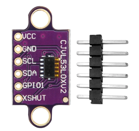
Overview
The ShillehTek VL53L0X is a Time-of-Flight (ToF) laser ranging sensor module built around ST Microelectronics' VL53L0X chip. Unlike ultrasonic or IR distance sensors, the VL53L0X measures distance by timing how long a Class-1 940 nm laser pulse takes to bounce off a target and return — which makes it immune to ambient light, color, and target reflectivity in ways that optical sensors can't match.
With a range of 30 mm to 2000 mm and ±3% typical accuracy, it's a perfect fit for robotics obstacle avoidance, drone altimetry, gesture sensing, presence detection, 3D scanning, liquid-level measurement, and any precision ranging project where a 10 mm-resolution reading matters. Because the sensor is only a few millimeters wide, it also fits in tight enclosures where an HC-SR04 would never go.
The module talks over I2C at the default address 0x29, runs on 2.6V to 5.5V (an onboard 2.8V LDO handles the chip's native voltage), and exposes an XSHUT pin so you can run multiple VL53L0X sensors on the same I2C bus by sequencing their addresses. It works great with Arduino, ESP32, Raspberry Pi, and Pico using the well-supported Adafruit and Pololu libraries.
At a Glance
Specifications
| Parameter | Value |
| Sensor Chip | ST VL53L0X |
| Ranging Technology | 940 nm Class 1 Laser (eye-safe) |
| Operating Voltage | 2.6V - 5.5V (onboard 2.8V LDO) |
| Operating Current | ~19 mA active, ~3 µA standby |
| Communication Protocol | I2C up to 400 kHz (Fast Mode) |
| Default I2C Address | 0x29 (7-bit, software configurable) |
| Range | 30 mm to 2000 mm |
| Ranging Accuracy | ±3% typical (good conditions) |
| Resolution | 1 mm |
| Ranging Modes | Default, High Accuracy, Long Range, High Speed |
| Timing Budget | 20 ms (default) - 200 ms (high accuracy) |
| Field of View | 25° typical |
| Operating Temperature | -20 °C to +70 °C |
| Dimensions | ~25 mm x 11 mm |
Pinout Diagram
Wiring Guide
Arduino Wiring
The VL53L0X runs cleanly on 5V thanks to its onboard LDO regulator. Connect SDA and SCL to the Arduino's hardware I2C pins (A4 and A5 on an UNO/Nano). XSHUT and GPIO1 are optional — you only need XSHUT for multi-sensor setups and GPIO1 for interrupt-driven reads.
| VL53L0X Pin | Arduino Pin |
|---|---|
| VCC | 5V |
| GND | GND |
| SCL | A5 (SCL) |
| SDA | A4 (SDA) |
| XSHUT | D2 (optional — multi-sensor) |
| GPIO1 | D3 (optional — interrupt) |
ESP32 Wiring
ESP32's default I2C pins are GPIO21 (SDA) and GPIO22 (SCL). Power the module from 3.3V or 5V — both work. Logic lines on the VL53L0X module are already 3.3V thanks to the onboard regulator and level-tolerant I/O, so no level shifter is required.
| VL53L0X Pin | ESP32 Pin |
|---|---|
| VCC | 3.3V (or 5V) |
| GND | GND |
| SCL | GPIO22 |
| SDA | GPIO21 |
| XSHUT | GPIO4 (optional) |
| GPIO1 | GPIO5 (optional) |
Wire.begin(sda, scl).
Raspberry Pi Wiring
Enable I2C first in raspi-config → Interface Options → I2C. The Pi's hardware I2C bus lives on physical pins 3 (GPIO2/SDA) and 5 (GPIO3/SCL).
| VL53L0X Pin | Raspberry Pi Pin (BOARD) |
|---|---|
| VCC | Pin 1 (3.3V) or Pin 2/4 (5V) |
| GND | Pin 6 (GND) |
| SCL | Pin 5 (GPIO3 / SCL) |
| SDA | Pin 3 (GPIO2 / SDA) |
| XSHUT | Pin 11 (GPIO17, optional) |
| GPIO1 | Pin 13 (GPIO27, optional) |
sudo i2cdetect -y 1. You should see 29 in the address grid — that confirms the sensor is talking.
Raspberry Pi Pico Wiring
The Pico has two I2C peripherals. We use I2C0 on GP0 (SDA) and GP1 (SCL) for the simplest pin arrangement, but any I2C-capable pair works.
| VL53L0X Pin | Pico Pin |
|---|---|
| VCC | 3V3(OUT) or VSYS (5V) |
| GND | GND |
| SCL | GP1 (I2C0 SCL) |
| SDA | GP0 (I2C0 SDA) |
| XSHUT | GP2 (optional) |
| GPIO1 | GP3 (optional) |
Code Examples
Arduino (Adafruit VL53L0X library)
// VL53L0X Time-of-Flight ranging
// Install: Arduino Library Manager → "Adafruit VL53L0X"
// Wiring: VCC->5V, GND->GND, SCL->A5, SDA->A4

#include <Wire.h>
#include "Adafruit_VL53L0X.h"

Adafruit_VL53L0X lox = Adafruit_VL53L0X();

void setup() {
  Serial.begin(9600);
  while (!Serial);

  Serial.println("VL53L0X: initializing...");
  if (!lox.begin()) {
    Serial.println("Failed to boot VL53L0X. Check wiring.");
    while (1);
  }
  Serial.println("VL53L0X ready.");
}

void loop() {
  VL53L0X_RangingMeasurementData_t measure;
  lox.rangingTest(&measure, false);

  if (measure.RangeStatus != 4) {  // 4 = out of range
    Serial.print("Distance (mm): ");
    Serial.println(measure.RangeMilliMeter);
  } else {
    Serial.println("Out of range");
  }
  delay(100);
}
Arduino (Long Range Mode)
// VL53L0X in Long Range mode (up to ~2m outdoors, ~1.5m in ambient light)
// Uses Pololu VL53L0X library for finer control
// Install: Arduino Library Manager → "VL53L0X by Pololu"

#include <Wire.h>
#include <VL53L0X.h>

VL53L0X sensor;

void setup() {
  Serial.begin(9600);
  Wire.begin();

  sensor.setTimeout(500);
  if (!sensor.init()) {
    Serial.println("Failed to detect VL53L0X");
    while (1);
  }

  // Long range: lower signal rate limit, wider pulse period
  sensor.setSignalRateLimit(0.1);
  sensor.setVcselPulsePeriod(VL53L0X::VcselPeriodPreRange, 18);
  sensor.setVcselPulsePeriod(VL53L0X::VcselPeriodFinalRange, 14);
  sensor.setMeasurementTimingBudget(33000); // ~33 ms

  sensor.startContinuous();
}

void loop() {
  uint16_t distance = sensor.readRangeContinuousMillimeters();
  Serial.print("Distance (mm): ");
  Serial.println(distance);
  if (sensor.timeoutOccurred()) Serial.println("Timeout!");
  delay(50);
}
Raspberry Pi (Python)
# VL53L0X on Raspberry Pi using Adafruit CircuitPython
# Install: pip install adafruit-circuitpython-vl53l0x --break-system-packages

import time
import board
import busio
import adafruit_vl53l0x

i2c = busio.I2C(board.SCL, board.SDA)
sensor = adafruit_vl53l0x.VL53L0X(i2c)

# Optional: extend timing budget for more accuracy (default 33000 us)
sensor.measurement_timing_budget = 200000  # 200 ms

print("VL53L0X ready. Reading distance...")
while True:
    try:
        distance = sensor.range
        print(f"Distance: {distance} mm")
        time.sleep(0.1)
    except KeyboardInterrupt:
        break
Raspberry Pi Pico (MicroPython)
# VL53L0X on Raspberry Pi Pico (MicroPython)
# Wiring: VCC->3V3, GND->GND, SCL->GP1, SDA->GP0
# Needs the VL53L0X MicroPython driver by Kevin McAleer:
# Copy vl53l0x.py from https://github.com/kevinmcaleer/vl53l0x_micropython
# onto the Pico filesystem.

from machine import I2C, Pin
from vl53l0x import VL53L0X
import time

i2c = I2C(0, sda=Pin(0), scl=Pin(1), freq=400000)
print("I2C scan:", [hex(a) for a in i2c.scan()])

tof = VL53L0X(i2c)
tof.start()

while True:
    distance = tof.read()
    print("Distance:", distance, "mm")
    time.sleep_ms(100)
ESP32 (MicroPython)
# VL53L0X on ESP32 (MicroPython)
# Wiring: VCC->3V3, GND->GND, SCL->GPIO22, SDA->GPIO21
# Upload vl53l0x.py driver to the board first (same driver as Pico).

from machine import I2C, Pin
from vl53l0x import VL53L0X
import time

i2c = I2C(0, scl=Pin(22), sda=Pin(21), freq=400000)
print("I2C scan:", [hex(a) for a in i2c.scan()])

tof = VL53L0X(i2c)
tof.start()

while True:
    print("Distance:", tof.read(), "mm")
    time.sleep_ms(100)
Frequently Asked Questions
setAddress(), then bring up the next one, and so on. This is a common robotics technique for 360-degree sensor rings.Adafruit_VL53L0X is the easiest to get started with and has great examples. Pololu's VL53L0X library exposes lower-level controls (signal rate limits, VCSEL pulse periods, custom modes) and is better if you need fine-grained tuning. Both are in the Arduino Library Manager.Related Tutorials
We don't have VL53L0X-specific tutorials on the ShillehTek blog yet — but we're working on projects like robot obstacle avoidance, multi-sensor arrays, and ToF-based gesture triggers. Subscribe to the newsletter to be the first to know.