

Overview
The ShillehTek Pro Micro ATmega32U4 5V 16MHz Presoldered (Type-C) is a compact, breadboard-friendly development board built around Atmel's ATmega32U4 microcontroller. Unlike the Arduino Uno or Nano, the ATmega32U4 has native USB built directly into the chip — no separate USB-to-serial converter required. This means the board can present itself to your computer as a keyboard, mouse, MIDI device, joystick, or generic serial port, which makes it one of the most popular choices for DIY macro pads, custom input devices, and USB HID projects.
The board runs at 5V and 16 MHz with 32 KB of flash, 2.5 KB of SRAM, and 1 KB of EEPROM. It exposes 18 digital I/O pins (5 with PWM), 9 analog inputs, hardware I2C, hardware SPI, and hardware UART. The headers come pre-soldered, so you can drop it straight into a breadboard and start building. Power is supplied through the USB Type-C connector or through the RAW pin (6–12V), and the onboard regulator provides 5V to VCC.
It programs just like a standard Arduino Leonardo using the Arduino IDE — select "Arduino Leonardo" or "SparkFun Pro Micro (5V, 16 MHz)" as the board, pick the COM port, and click Upload. Libraries like Keyboard, Mouse, and HID-Project unlock the native USB capabilities that make this board so much fun to build with.
At a Glance
Specifications
| Parameter | Value |
| Microcontroller | Atmel ATmega32U4 |
| Operating Voltage | 5V |
| Input Voltage (RAW) | 6–12V (onboard regulator) |
| Clock Speed | 16 MHz (external crystal) |
| Flash Memory | 32 KB (4 KB used by bootloader) |
| SRAM | 2.5 KB |
| EEPROM | 1 KB |
| Digital I/O Pins | 18 total |
| PWM Pins | 5 (D3, D5, D6, D9, D10) |
| Analog Inputs | 9 (A0–A3, A6–A10) |
| Hardware Interfaces | 1x UART, 1x I2C, 1x SPI |
| External Interrupts | 5 (D0, D1, D2, D3, D7) |
| DC Current per I/O Pin | 20 mA (40 mA absolute max) |
| USB Connector | USB Type-C (native USB 2.0 device) |
| Dimensions | 33 × 18 mm |
| Bootloader | Caterina (Arduino Leonardo compatible) |
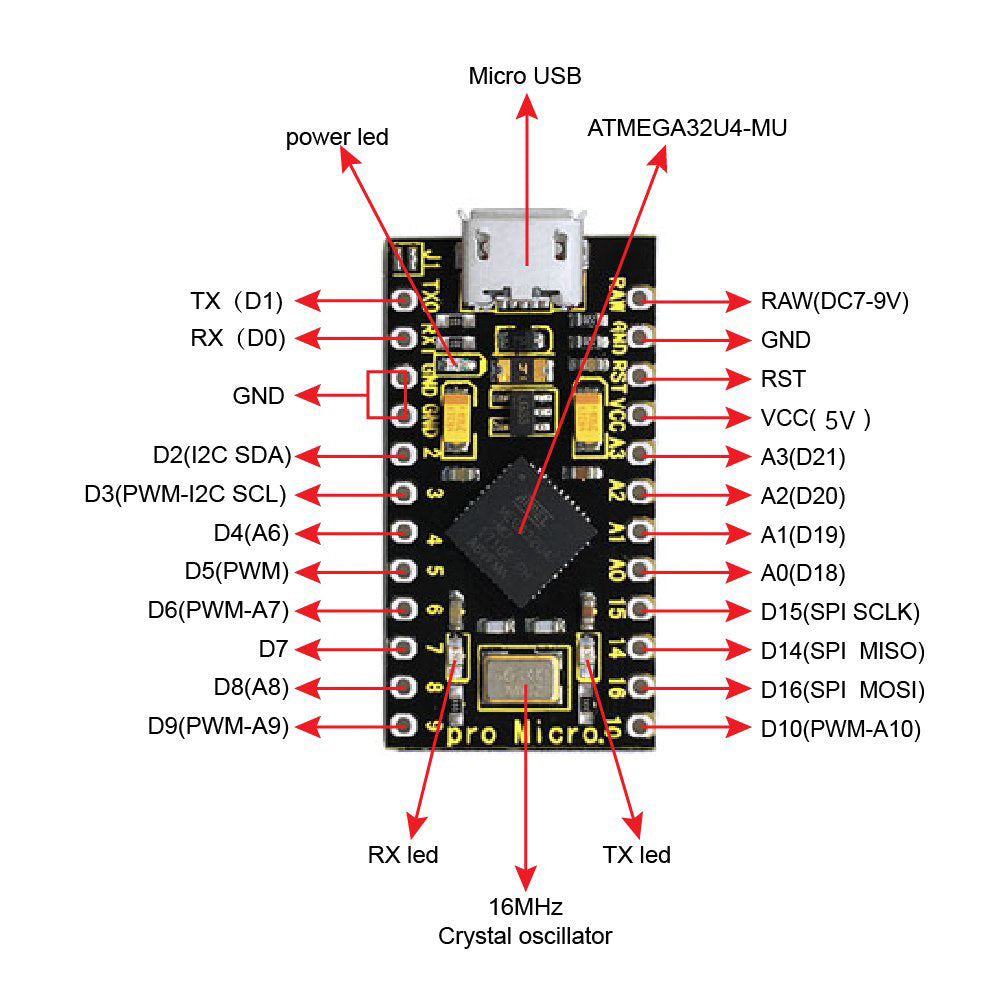
Pinout Diagram
Wiring Guide
Arduino IDE Setup
The Pro Micro uses the Caterina bootloader, which is the same bootloader used by the Arduino Leonardo. You can use either the built-in Leonardo board definition or install SparkFun's Pro Micro board support for more accurate board naming.
| Setting | Value |
|---|---|
| Board | Arduino Leonardo (or SparkFun Pro Micro) |
| Processor (if Pro Micro) | ATmega32U4 (5V, 16 MHz) |
| Port | COM or /dev/ttyACM* that appears when plugged in |
| Programmer | AVRISP mkII (default) |
Power Options
The Pro Micro can be powered three ways. Pick whichever fits your project.
| Method | Pin | Voltage Range |
|---|---|---|
| USB Type-C | USB connector | 5V (from host) |
| Regulated input | VCC pin | 5V only (bypasses regulator) |
| Unregulated input | RAW pin | 6–12V (goes through onboard regulator) |
I2C Peripherals
The ATmega32U4 has one hardware I2C port using pins D2 (SDA) and D3 (SCL). Use the standard Wire library to talk to sensors and displays.
| Pro Micro Pin | I2C Signal | Connect To |
|---|---|---|
| D2 | SDA | Peripheral SDA |
| D3 | SCL | Peripheral SCL |
| VCC | — | Peripheral VCC (if peripheral is 5V-tolerant) |
| GND | — | Peripheral GND |
SPI Peripherals
The ATmega32U4 exposes hardware SPI on the 6-pin ICSP-style header as well as on dedicated through-holes. Use the SPI library with any pin you prefer as CS.
| Pro Micro Pin | SPI Signal | Direction |
|---|---|---|
| D15 | SCK | Output |
| D16 | MOSI | Output |
| D14 | MISO | Input |
| Any digital pin | CS/SS | Output (software) |
digitalWrite(11, ...) to bit-bang SPI, change those references to the correct SPI pins (D14/D15/D16).
Code Examples
Blink (Hello World)
// Blink the onboard TX/RX LEDs since the Pro Micro has no
// dedicated user LED on a GPIO pin. D13 is not an LED here.

void setup() {
  // Both built-in LEDs are available:
  // LED_BUILTIN_TX (PD5) and LED_BUILTIN_RX (PB0)
  pinMode(LED_BUILTIN_TX, OUTPUT);
  pinMode(LED_BUILTIN_RX, OUTPUT);
}

void loop() {
  digitalWrite(LED_BUILTIN_TX, LOW);   // LEDs are active-LOW
  digitalWrite(LED_BUILTIN_RX, HIGH);
  delay(500);
  digitalWrite(LED_BUILTIN_TX, HIGH);
  digitalWrite(LED_BUILTIN_RX, LOW);
  delay(500);
}
USB Keyboard (Native HID)
// Wire a pushbutton between D2 and GND.
// When pressed, the Pro Micro types "Hello from Pro Micro!"
// as if it were a real USB keyboard.

#include <Keyboard.h>

const int BUTTON_PIN = 2;
bool lastState = HIGH;

void setup() {
  pinMode(BUTTON_PIN, INPUT_PULLUP);
  Keyboard.begin();
}

void loop() {
  bool state = digitalRead(BUTTON_PIN);

  // Trigger on press (HIGH -> LOW transition)
  if (lastState == HIGH && state == LOW) {
    Keyboard.print("Hello from Pro Micro!");
    Keyboard.press(KEY_RETURN);
    Keyboard.releaseAll();
    delay(50);  // debounce
  }

  lastState = state;
}
USB Mouse Jiggler
// Classic "mouse jiggler" — moves the cursor a pixel every
// 30 seconds so your computer thinks you're still at it.

#include <Mouse.h>

void setup() {
  Mouse.begin();
}

void loop() {
  Mouse.move(1, 0, 0);
  delay(100);
  Mouse.move(-1, 0, 0);
  delay(30000);  // 30 seconds
}
I2C Scanner
// Scans the I2C bus and prints the address of every device
// it finds. Useful first sketch to verify SDA/SCL wiring.

#include <Wire.h>

void setup() {
  Wire.begin();
  Serial.begin(9600);
  while (!Serial) { ; }  // Wait for native USB CDC port
  Serial.println("I2C Scanner");
}

void loop() {
  byte found = 0;

  for (byte addr = 1; addr < 127; addr++) {
    Wire.beginTransmission(addr);
    if (Wire.endTransmission() == 0) {
      Serial.print("Device at 0x");
      if (addr < 16) Serial.print("0");
      Serial.println(addr, HEX);
      found++;
    }
  }

  if (found == 0) Serial.println("No devices found");
  delay(5000);
}
Media Control Keys (Consumer HID)
// Turns the Pro Micro into a media control remote.
// Requires the HID-Project library (install via Library Manager).
// Wire three buttons: D2=Play/Pause, D3=Next, D4=Previous.

#include <HID-Project.h>

const int PLAY_PIN = 2;
const int NEXT_PIN = 3;
const int PREV_PIN = 4;

void setup() {
  pinMode(PLAY_PIN, INPUT_PULLUP);
  pinMode(NEXT_PIN, INPUT_PULLUP);
  pinMode(PREV_PIN, INPUT_PULLUP);
  Consumer.begin();
}

void loop() {
  if (digitalRead(PLAY_PIN) == LOW) {
    Consumer.write(MEDIA_PLAY_PAUSE);
    delay(200);
  }
  if (digitalRead(NEXT_PIN) == LOW) {
    Consumer.write(MEDIA_NEXT);
    delay(200);
  }
  if (digitalRead(PREV_PIN) == LOW) {
    Consumer.write(MEDIA_PREVIOUS);
    delay(200);
  }
}
Frequently Asked Questions
Keyboard.begin()/Serial.begin(), the port may not come back. Double-tap the RST pin to GND to force the bootloader to stay active for 8 seconds so you can upload a new sketch.Keyboard and Mouse libraries for basic use, or the HID-Project library for advanced features like media keys and gamepad reports.LED_BUILTIN_TX and LED_BUILTIN_RX, and they're active-LOW (write LOW to turn them on). Most Blink examples need to be adjusted accordingly.Related Tutorials
No tutorials specific to the Pro Micro ATmega32U4 are published on shillehtek.com yet. Check back soon — new projects using this board (keyboard macropads, mouse jigglers, USB gadgets) will be added here as they go live.